4 Wireless TimeClock Configuration Guide
Connect the Wiring
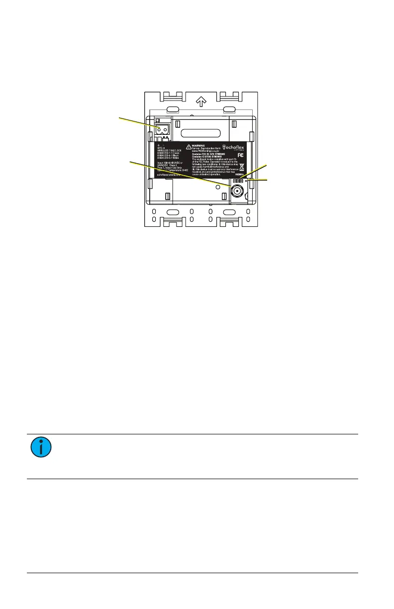
The WTC ships with a 24 V power terminal strip with wire pigtail, spacers,
and all required screws and connectors for the installation.
24 V power pigtail
receptacle
RP-SMA connector
port for external
antenna
Jumper setting
for antenna
Internal whip
antenna
The antenna jumper is set to use the internal whip antenna by default, pos-
ition 2 and 3. If your installation uses the external antenna option, adjust
the jumper position to 1 and 2 (move it left).
1. Pull the two 24 V power supply wires into the electrical box and strip
11mm (7/16 in) of insulation.
2. Strip 11 mm (7/16 in) of insulation from both the red and black pigtail
wires.
3. Use the WAGO connectors provided to connect the power pigtail and
the power supply output wires. Use one WAGO for the red wire
(positive +) and one for the black wire (negative -). Open the terminal
levers on the WAGO connector and insert the power supply wire and
the lead from the pigtail into the terminals, then close the levers. Tug
the wires to ensure they are secure.
4. Connect the two-pin connector to the power pigtail receptacle on the
station.
5. If using the external antenna option, connect the patch cable to the
RP-SMA connector port. Ensure the jumper is set to position 1 and 2.
Note: If using the External Antenna Extension kit, the connection
for the flexible coaxial patch cable (part number N1124) may be out-
side the electrical box. See Accessories.