EVER UPS SINLINE RT / RT XL series instruction manual
Pomoc Techniczna, tel.: +48 61 6500 400
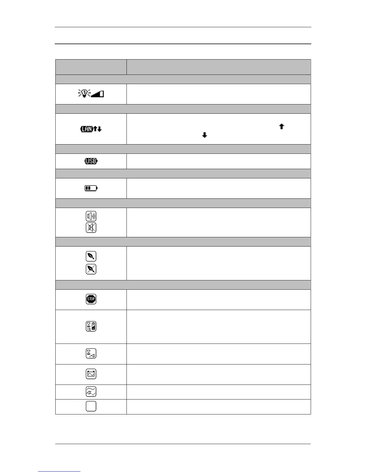
DESCRIPTION OF LCD DISPLAY ICONS
Table 3. Description of LCD display icons
1 – UPS output load indicator
Load level signaling. Further segments of the icon light up while the load
increases.
2 – LAN connection indicator
Signal confirming that the UPS is connected to LAN and visualization of the
direction of transferred data. Packets sent to the network (icon ), packets
received from the network (icon ).
3 - USB connection indicator
The icon is displayed if the UPS is connected with the PC through USB.
4 - Battery charge level indicator
Battery charge level indicator. Further segments of the icon light up as the
battery charge level increases.
5 - MUTE function indicator
Icon indicating the activation / deactivation of sound signal when the UPS is in
back-up (battery) mode. The UPS alarm states is not muted.
6 – GREEN function indicator
Icon activating / deactivating the function of saving energy stored in the
batteries. When the UPS is in back-up (battery) mode and there are no
receivers connected or power consumption is below the threshold value of 30
W, the UPS will automatically switch off after 15 minutes.
7 – UPS operation indicator
The icon is displayed if one of the following operation modes is activated:
EMERGENCY, STOP or READY.
The UPS is on logically, the mains parameters are correct. After the UPS
switches from the STANDBY mode, the unit waits until the battery is charged to
a minimal, required level declared in % (CONFIGURATION; UPS; STB
Charge).
The UPS operates in STANDBY mode. The mains voltage fails to satisfy the
correctness criteria, the UPS is on logically.
The UPS operates in back-up (battery) mode - there is no mains power supply
or threshold frequency value or effective value of supply voltage are exceeded.
The UPS operates in mains (normal) mode.
The UPS operates in INIT (initialization) mode.