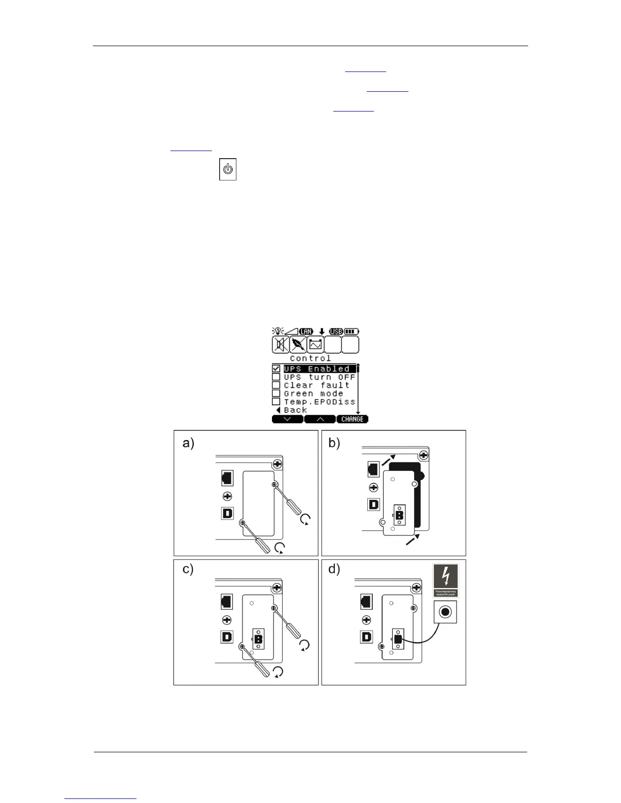
3. Undo the screws of the expansion slot cover (Fig. 49a).
4. Insert the card, making sure it is aligned properly (Fig. 49b).
5. Install the card slot cover to the rear panel (Fig. 49c).
6. Connect an external EPO circuit - a fire protection breaker - to the card's
connector (Fig. 49d).
7. Press and keep the key on the UPS unit's front panel depressed for over 1
second to switch the device on.
8. Switch on the UPS logically with the control panel (MENU; CONTROL sub-menu;
UPS Enabled).
9. If the card has been correctly installed and identified by the UPS, the
Temp.EPODiss - temporary EPO input deactivation (1 min.) parameter appears
in the CONTROL sub-menu.
Fig. 49: Installation of the card in the UPS