DreamCatcher Replay System
Page 8 Revision 1.13
DreamCatcher
Controller 1
ETH 0
DreamCatcher
Controller 2
DC-LOGGER
DreamCatcher
Server 1
10G IPX Switch
(When connecting 3
or more systems)
DreamCatcher
Server 2
1G Isolated
DreamCatcher
Network
10G
10G
ETH 0
ETH 0
ETH 0
ETH 0
ETH 2
ETH 2
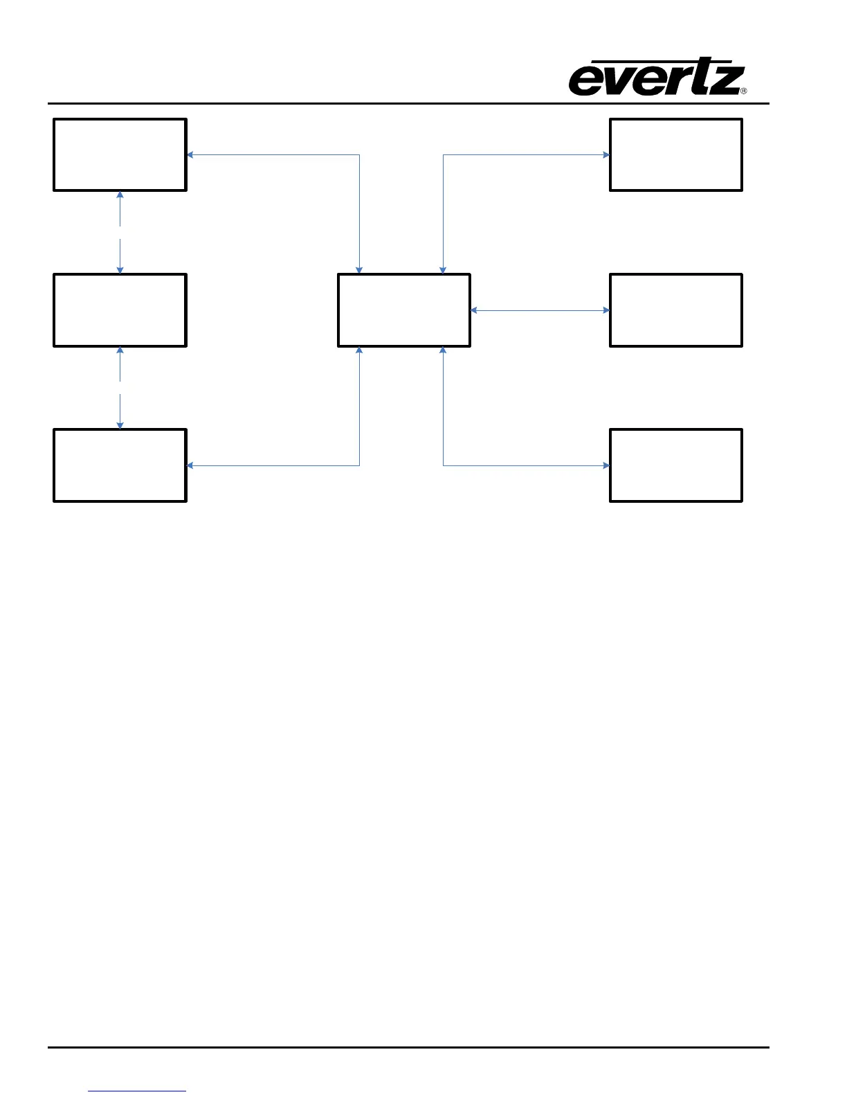
Figure 2-5: Distributed DreamCatcher Control Networking
Use Figure 2-1, Figure 2-2 and Figure 2-6 as reference.
If DreamCatcher needs to interact with other infrastructure equipment (i.e. routers, production
switcher and engineering PCs) add a second 1G Ethernet switch.
Connect Ethernet 1 on all DreamCatcher servers to the 1G Infrastructure switch.
Connect Ethernet B/1 on all DreamCatcher Controllers to the 1G Infrastructure switch.
 Loading...