DreamCatcher Replay SystemDream Catcher
Revision 1.13 Page 11
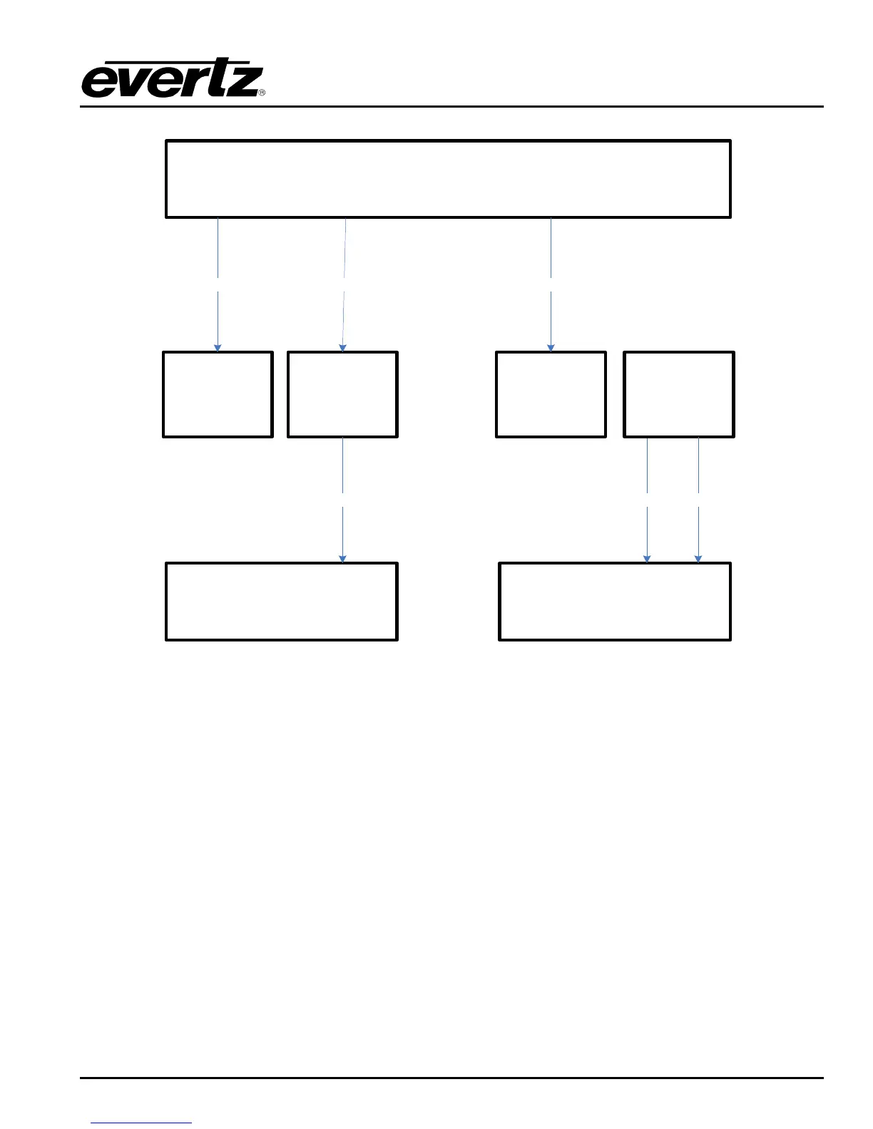
DreamCatcher Server 1
DreamCatcher Controller 2
Monitor Touch Monitor
DVI DVI
DVI Display Port 1
USB
USB B
USB A
DreamCatcher Controller 1
Monitor Touch Monitor
USB
DVI
DVI
Display Port 2
USB B
USB A
Figure 2-8: Single Server and Dual Controller, 4 Monitor Setup
2.7. GENLOCK
DreamCatcher currently requires a Black Burst reference signal. Plug the reference signal into DIN 1 at
the back of DreamCatcher as shown on Figure 2-1 and Figure 2-9.
To check the reference standard follow the setup in section 3.3.1 and section 3.4.2.1 to get to
DreamCatcher‟s Configuration page. Once on the page you should see reference detected as NTSC or
PAL.
2.8. INPUT/OUTPUTS
DreamCatcher‟s Inputs and Outputs can be dynamically configured using the web configuration
application. For this reason the labelling on the back of DreamCatcher may not be accurate. Using Figure
2-1, follow these general rules for cabling inputs and outputs.
Connect output 1 to the DIN connector immediately adjacent to the reference signal connector. In
Figure 2-1 this would be the second DIN from the bottom.
 Loading...