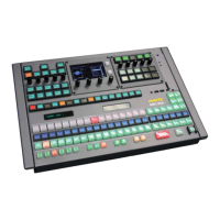
EMC-DCP
EMC DESKTOP CONTROL PANEL
Revision 1.1 Page 7
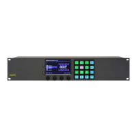
Description
1
Protective covers: The EMC-
DCP panel will ship with the protective covers installed.
When installing the panel into a 19” wide rack, the protective covers should be removed.
2
Large LCD button: The functions of these buttons are configured using the EMCSetup
software. This button type supports 255 different colours.
3
Shaft Encoders: The shaft encoders are used to scroll through values on the large
LCD button directly above it.
4
Small LCD buttons: The functions of these butto
ns are configured using the
EMCSetup software. The button type supports 255 different colours.
5
VFD Displays:
The VFD displays are used to provide the operators with information
regarding the panel and channel.
6
Large LED buttons: The functions of these buttons are configured using the
EMC
Setup software. This button type supports the colours Red and Green (and a
combination of the two colours).
7
Small LCD displays: These LCD displays function as displays only. They display the
names of the Large
LED buttons above the row of LCD displays. This display type
supports 255 different colours.
8
Small LED buttons: The functions of these buttons are configured using the
EMC
Setup software. This button type supports the colours Red and Green (and a
combination of the two colours).
9
Fan Status LEDs: These LEDs indicate the status of the EMC-DCP cooling fans.
10
Cooling Fan unit: This is the cooling fan unit of the EMC-DCP. It can be serviced from
the top surface of the EMC-DCP.
11
Extra USB Ports: These ports are designated for future use. Currently, a protective
cover is installed.
12
Double LED button:
The functions of these buttons are configured using the
EMCSetup software. This button type only supports the colour Red.
13
Pin Hole Reset: The Reset pin hole is on the left side and can be used to reset the
panel. The Pin Hole Reset is used in case access to the EMC-DCP power switch is
blocked.
Pin Hole Power: The Power pin hole is on the right side and can be used to completely
power off the unit. The Pin Hole Power is used in case access to the EMC-DCP power
14
Small LED button: This small LED has the same function as item 8. However, the
small LED button is protected by a finger guard to prevent operators from accidentally
Table 3-1: EMC-DCP – Top Surface Descriptions