EMC-DCP
EMC DESKTOP CONTROL PANEL
Revision 1.1 Page 9
GPIO: DB-25 connector. Used for panel generated GPIs and GPOs.
ETHERNET A: RJ45 connector. Used for Network connections from EMC-DCP to 3025EMC, QMC-
2 and QMGs.
ETHERNET B: RJ45 connector. Used for Network connections from EMC-DCP to 3025EMC, QMC-
2 and QMGs.
USB 1 to 4: USB 2.0 Ports. Used for USB-based mouse, keyboard, and storage device
connections.
SERIAL A to D: RS232/422 DB-9 connectors. Not used.
SERIAL E: RS232 DB-9 connector. Not used.
Q-LINK 1, 2 IN: BNC connector. Used for Q-LINK connection to the EMC-DCP. Currently not
supported.
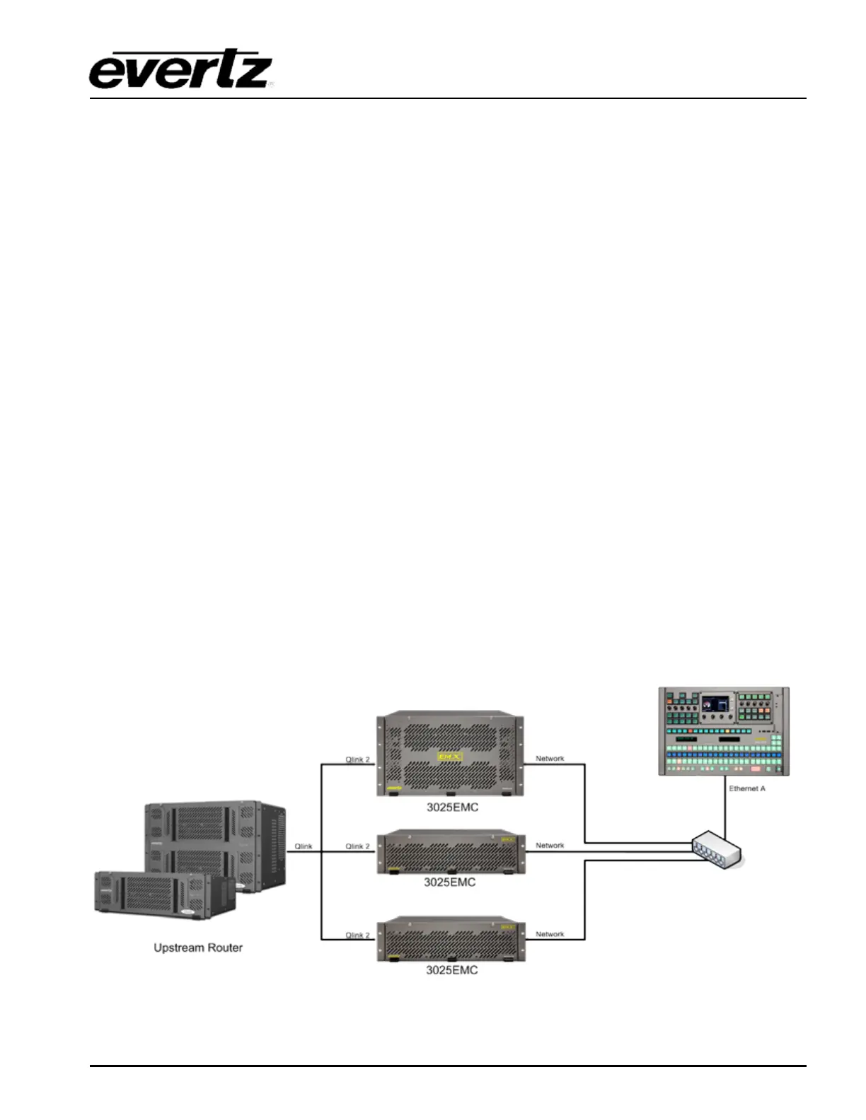
3.4. CONNECTING EMC-DCP TO 3025EMC SYSTEM
The EMC-DCP is an extension of the existing family of control panels for the EMC Master Control
systems. Like the previous QMC-DCP, the EMC-DCP will communicate with the EMC over an Ethernet
connection.
Error! Reference source not found. shows a basic EMC System configuration. The EMC will still
communicate with an upstream router via Q-Link or Serial (if router is a third party router). To connect
the EMC-DCP to the EMC, a network hub/switch is required. Connect a Cat 5 Ethernet cable from
Ethernet A (on EMC-DCP) to the network hub. The user will then connect a Cat 5 Ethernet cable to the
Network Port of the EMC. Use the EMCSetup software to setup the IP addresses, network settings,
etc. (See section 3.8).
Figure 3-6: Basic EMC Configuration