Mechanical Installation
48
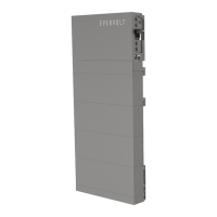
Step 2: Mount the inverter
a) Two M4 holes are reserved on the BMS for fixing the bracket of the
inverter.
Ÿ Screw in M4 screws to pre-fix the bracket on the BMS but be sure not to
tighten.
Ÿ Hold the bracket firmly to the wall surface.
Ÿ Tighten the M4 screws to fix the bracket on the BMS.
M4
4.4 lbf.in /
0.5 N·m
b) Use the bracket as the template to mark the screw hole location on the
wall;
Round holes
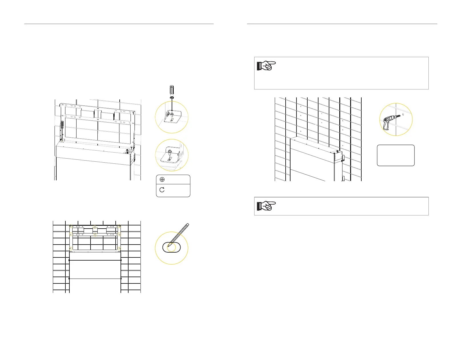
c) Unscrew the two M4 screws to disassemble the bracket. Drill holes with
power drill, and make sure the holes are deep enough (2.16 in / 55 mm) to support
the inverter.
The figure below is only used for showing the depth and location of
holes. Make sure the holes are in the center of each stud and keep at
least 1.49 in / 38 mm away from the edge of concrete bricks or
studs before marking holes.
NOTE!
Depth:
2.16 in / 55 mm
Φ4 drill
For solid concrete wall, please use Φ10 drill.
NOTE!
Mechanical Installation
49