204
POWERHEAD
POWERHEAD DISASSEMBLY
POWERHEAD
DISASSEMBLY
General
To simplify reassembly and wiring installation, lay
out the various screws and clamps in the order of
their proper location.
Remove the electric starter. Refer to Starter
Removal on p. 144.
Remove the oil tank. Refer to Oil Tank Assembly
on p. 187.
Remove fuel pump assemblies, fuel manifolds,
and filter. Refer to FUEL COMPONENT SERVIC-
ING on p. 166.
Remove EMM and electrical harness assembly.
Refer to EMM SERVICING on p. 102.
Remove flywheel and stator. Refer to FLYWHEEL
AND STATOR SERVICING on p. 139.
Remove ignition coils and fuel injectors. Refer to
Fuel Injector Service on p. 169.
IMPORTANT: Mark injectors for cylinder loca-
tion before removal. All injectors must be installed
in their original location. Improper injector installa-
tion can result in powerhead failure.
Remove throttle linkage. Refer to Throttle Link-
age Removal on p. 204.
Remove shift linkage. Refer to Shift Linkage
Removal on p. 204.
Remove the throttle body and reed plate assem-
blies. Refer to Intake Manifold Service on p. 172.
Remove pressure valve assembly. Refer to
PRESSURE RELIEF VALVE SERVICING on
p. 197.
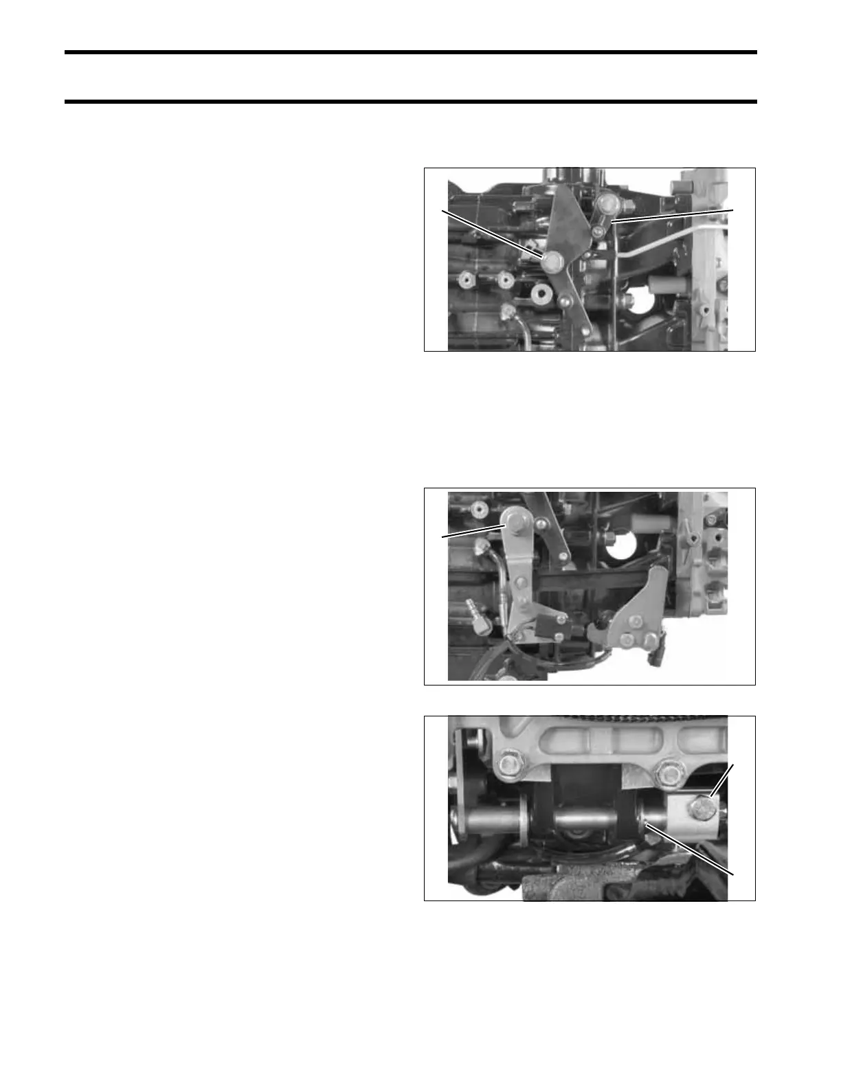
Throttle Linkage Removal
Remove throttle cam and throttle lever.
Shift Linkage Removal
Remove shoulder screw from shift arm and retain-
ing screw from shift rod lever. Remove the cotter
pin and washer holding the shift shaft.
Slide entire shift linkage assembly from crank-
case.
1. Throttle lever screw
2. Throttle return lever
002245
1. Shift lever screw 002250
1. Shift rod lever screw
2. Cotter pin
002246
21
1
1
2