51
INSTALLATION AND PREDELIVERY
OUTBOARD RIGGING
2
CANbus Connections
If the outboard will be used with I-Command, or
other NMEA 2000 compliant CANbus instruments,
the following connections will supply information
to the network.
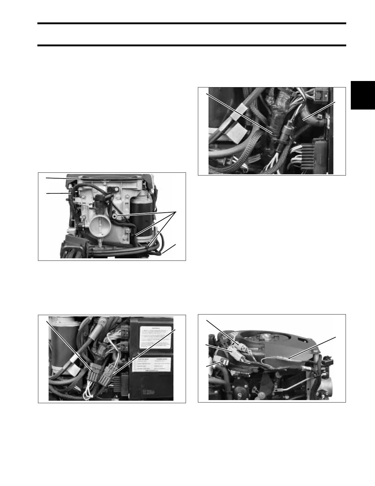
Remove lower motor covers. Remove air silencer.
Route CANbus network harness around the front
of the throttle body, following the path of the TPS
wiring, and behind the battery cable. Loosely
install tie straps as shown.
IMPORTANT: To prevent wire chafing, harness
must be routed below the flywheel cover.
Remove protective cap from the EMM CANbus
connector and connect to the CANbus network
harness.
To prevent interference with engine cover latch,
bundle excess wiring behind EMM cooling water
hose. Secure CANbus connectors to back side of
engine harness with tie strap.
Adjust harness routing as needed and secure tie
straps.
Use a CANbus Ignition Harness, in place of the
standard MWS harness, to connect the outboard
to the key switch and trim/tilt control. Seal unused
SystemCheck connector with 6-Pin Connector
Seal, P/N 586076.
If installing a Deutsch-style network, connect the
purple wire from the CANbus Ignition Harness to
the CANbus network harness. This connection
supplies power to the network when the key
switch is on. Quick Connect-style network does
NOT use this connection.
1. Flywheel cover
2. Harness routing
3. Tie straps
006736
1. Canbus network connector
2. EMM CANbus connector and cap
006735
3
2
1
2
2
1
1. Engine harness
2. EMM cooling water hose
006738
1. Trim/Tilt connector
2. CANbus Ignition connector
3. SystemCheck connector (with seal)
4. Deutsch-style harness power connector
006734
2
1
4
1
2
3