220
POWERHEAD
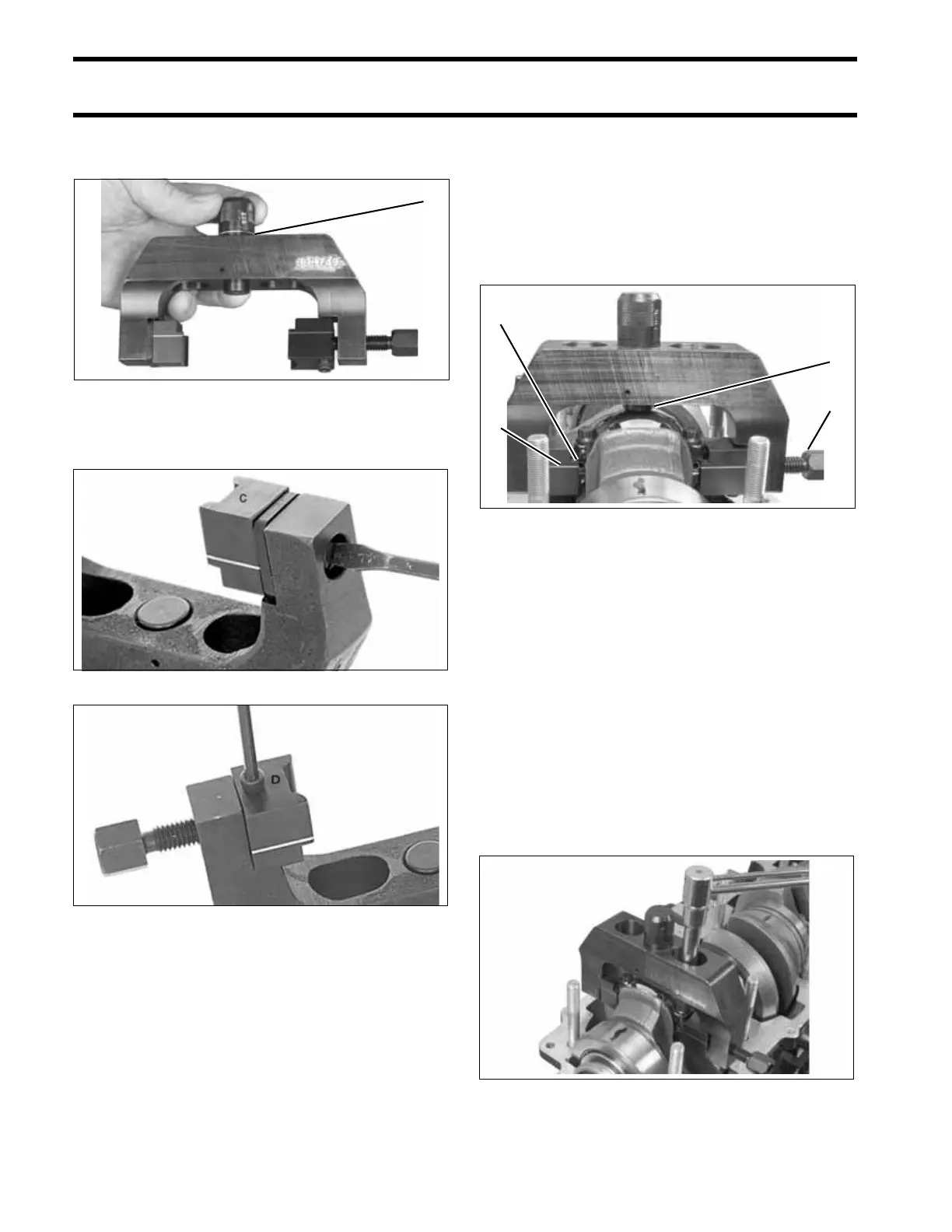
POWERHEAD ASSEMBLY
setting (one line showing). Rotate adjustment
knob 180° to lock in position.
Secure restraining jaw “C” and forcing jaw “D” to
frame.
Apply a light coat of outboard lubricant to the cor-
ners of the connecting rod and rod cap. Place
frame on connecting rod using the following pro-
cedure.
• Position frame onto the connecting rod so the
contact area of the jaw is centered on the side
of the rod.
• Tighten forcing screw until jaws contact con-
necting rod.
• Slide frame down until adjustment stop contacts
the rod cap. The groove lines on the jaws must
be centered on the rod/crankpin diameter.
• Tighten the forcing screw to a torque of 14 to 16
in. lbs. (1.6 to 1.8 N·m).
IMPORTANT: Make sure that frame is squarely
in position and that rod and cap are aligned.
Loosen both rod cap screws one-quarter turn.
Use Torquing Socket, P/N 331638, to tighten rod
cap screws in three stages:
• Apply first torque of 40 to 60 in. lbs. (5 to 7 N·m)
to both rod cap screws.
• Tighten screws to a torque of 14 to 16 ft. lbs. (19
to 21.7 N·m).
• Apply final torque of 30 to 32 ft. lbs. (41 to 43
N·m).
1. Center position, one line showing 002484
Restraining Jaw “C” 21591
Forcing Jaw “D” 21594
1
1. Contact area of jaw
2. Forcing screw
3. Adjustment stop
4. Groove line
002071
002072
3
2
1
4