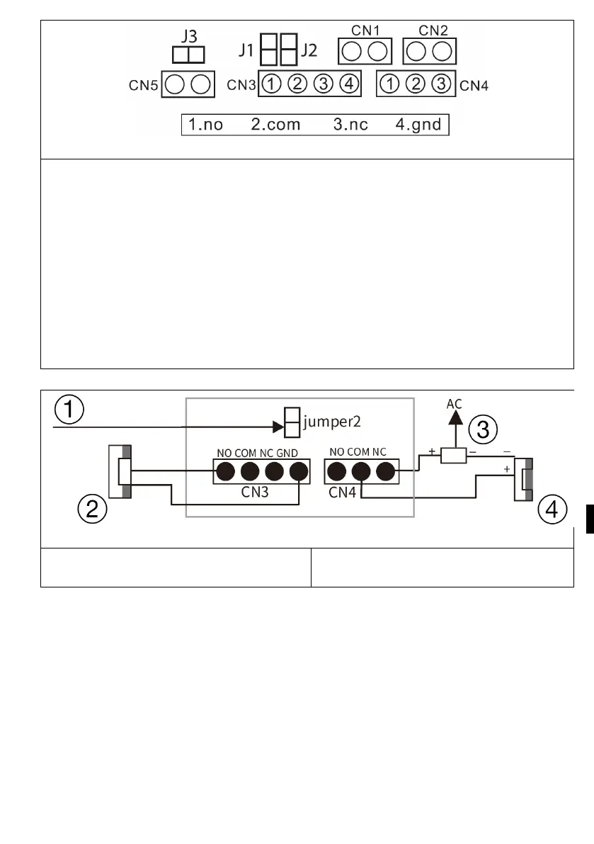
57
1. NO 2. COM 3. NC 4. GND
jumper 2: connect as CN3 power output, disconnect as CN3 without power
output.
jumper 1: disconnection as CN3 for connection of electronic lock.
jumper 3: for door station ID, connection as id 1, disconnection as id 2.
CN1: for the lock end button CN3.
CN2: for the lock end button CN4.
CN3: To lock 1 (the door station can offer power to the electronic lock, th
e
m
agnetic lock must be connected to an external power source).
CN4: To lock 2 (lock must be connected to external power supply, NO and COM
connected to magnetic lock, NC and COM connected to electronic lock).
Detailed connection With the lock diagram
1) connection as Output power
2) electric lock
3) power supply
4) Magnetic lock