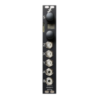
B-6 Clockable LFO
Video
X is clock input
Y is waveshape
Z is integer multiplier/divider
A is saw -> sine -> triangle
B is pulse -> square -> pulse
Tap tempo enabled
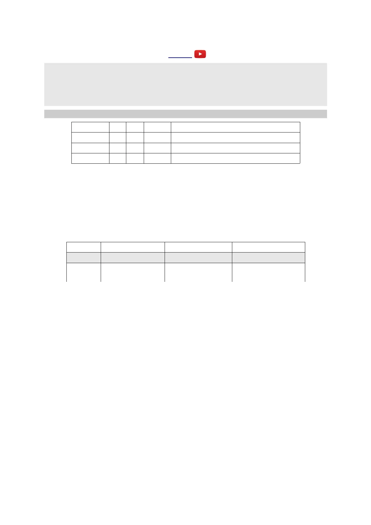
Parameter Min Max Default Description
0 -32 32 32 Output A attenuverter.
1 -32 32 32 Output B attenuverter.
2 -32 32 0 Y Offset.
Outputs A & B are LFOs (low frequency oscillators), with CV control of waveshape, and with the
LFO cycle time set from a clock input. The output signals are ±8V (16V peak-to-peak) by default,
but can be attenuated and inverted via parameters 0 & 1.
Input X is the clock input. Any clock pulse in excess of 1V can be used. The time between rising
trigger edges is used to set the cycle time.
Input Y controls the waveshape of the output signals. Signals in the range ±5V give the full range of
possible waveshapes:
Input Y -5V 0V +5V
Output A saw sine triangle
Output B 0% duty cycle pulse
50% duty cycle pulse
(square)
100% duty cycle pulse
Parameter 2 is an offset added to the Y CV, allowing manual selection of the waveshape.
The Z knob/CV sets a scale factor which is applied to the cycle time. The scale is an integer (whole
number) which either multiplies or divides the frequency, and ranges in value from 1-16.
When Z changes, the scale is shown on the display. If the value shown is negative, it is a divisor
rather than a multiplier. Note that there is no value of "-1" since dividing by 1 and multiplying by 1
are the same.
Page 30
 Loading...