X is the modulator input, and Y is the carrier input.
A is the audio output. B outputs a CV related to the envelope of the modulator signal.
The Z control sets the decay time of the internal envelope trackers, which track each band of the
modulator signal. Use low values (negative Z) for most intelligible speech.
Parameter 0 selects between alternative filter banks:
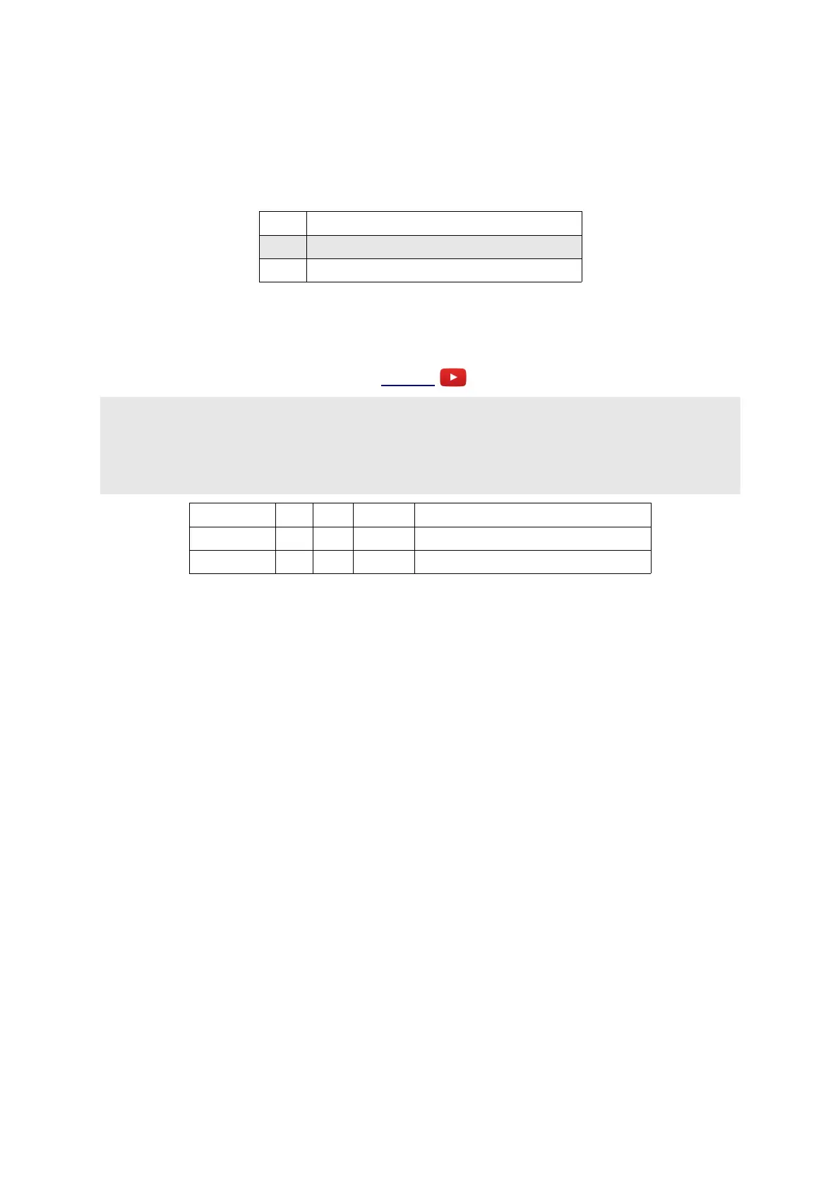
Bank Description
0 Half octave spacing, based on 100Hz.
1 Third octave spacing, based on 250Hz.
Parameters 1 & 2 provide attenuation or gain of outputs A & B respectively.
C-7 Phaser
Video
X is audio input
Y is sweep
Z is feedback (bipolar)
A is phase-shifted output plus input signal
B is phase-shifted output
Parameter Min Max Default Description
0 -31 31 0 Applies an offset to the Y input.
1 1 10 10 Sets the number of phaser stages.
This algorithm implements a phase shifter or 'phaser' effect.
X is the audio input.
Y is the sweep input. 0V to 8V covers the whole range; negative voltages are treated as 0V. You
will almost always want to patch an LFO in here. Parameter 0 can be used to set this to a 'centre'
value, which makes it easier to patch in an LFO to the Y input without having to add a DC offset to
the LFO.
Z controls feedback. More feedback results in more extreme phasing effects. When Z is negative,
the feedback is inverted, which gives a different-sounding phasing effect.
A outputs the combination of the phase-shifted signal and the original signal, which is usually what
you need for a classic phaser effect, since it's the interaction of the original signal and the phase-
shifted version which produces the 'comb filtering' effect.
Output B provides just the phase shifted signal, if you need more control over how this and the
original signal are mixed.
Parameter 1 sets the number of phase shifting stages. The more stages, the more notches there are in
the comb filter, which results in a more pronounced effect.
Page 37
 Loading...