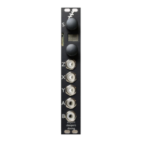
Input X is the signal input. Any audio signal can be fed in here.
Input Y is the clock input. Any clock pulse in excess of 1V can be used. The time between rising
trigger edges is used to set the delay time. If the time between triggers is greater than the maximum
delay time, the time is divided by two until it is small enough. This way, you always end up with a
rhythmically useful delay time.
Parameter 1 applies a multiplier to the delay time, according to the table above.
The Z knob/CV controls the feedback, from zero to slightly more than 100%.
Outputs A & B are the left and right outputs respectively.
Parameter 0 controls the output mix between the dry signal and the delay signal. At the default
value of -33, the amount of delay in the mix rises in direct proportion to the amount of feedback.
For values from -32 to 0, the output crossfades between the delay (at -32) and the dry signal (at 0).
For values above 0, the dry signal level is constant and the delay signal level rises with the
parameter value.
Parameter 2 controls the left/right pan position of the input signal.
C-4 Clockable Ping Pong Delay (Z input pan)
Video
X is audio input
Y is clock
Z is input pan
A is left output
B is right output
Tap tempo enabled
Parameter Min Max Default Description
0 0 31 24 Feedback.
1 -15 8 0 Delay time multiplier.
2 -33 32 -33 Mix.
This algorithm is a stereo ping-pong delay/echo effect, primarily intended for processing audio
signals, where the delay time is set from a clock pulse. It operates at a quarter of the standard
sample rate (i.e. at about 19kHz) and offers a maximum delay time of about 900ms.
Input X is the signal input. Any audio signal can be fed in here.
Input Y is the clock input. Any clock pulse in excess of 1V can be used. The time between rising
trigger edges is used to set the delay time. If the time between triggers is greater than the maximum
delay time, the time is divided by two until it is small enough. This way, you always end up with a
rhythmically useful delay time.
Parameter 1 applies a multiplier to the delay time, according to the table above.
The Z knob/CV controls the left/right pan position of the input signal.
Outputs A & B are the left and right outputs respectively.
Parameter 2 controls the output mix between the dry signal and the delay signal. At the default
value of -33, the amount of delay in the mix rises in direct proportion to the amount of feedback.
For values from -32 to 0, the output crossfades between the delay (at -32) and the dry signal (at 0).
Page 35
 Loading...