according to the table above.
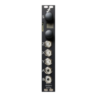
F-8 Shift Register Random Dual Triggers
Video
X is clock input
Y is modify input
Z sets the randomness
A is trigger output A
B is trigger output B
Press Z to modify sequence
Receives MIDI
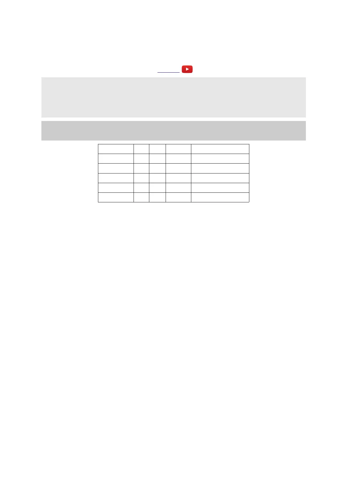
Parameter Min Max Default Description
0 1 32 8 Length A.
1 1 32 8 Length B.
2 0 31 0 Pulse A.
3 0 31 0 Pulse B.
4 0 15 0 MIDI clock divisor.
This algorithm generates random triggers via the popular rotating shift register method. The joy of
this method is that it generates a loop of triggers, with a controllable likelihood of change, including
the possibility to lock the loop so it does not change. In this algorithm there are two shift registers
for the two outputs, which share a common clock.
X is the clock input. Any clock pulse in excess of 1V can be used. On each rising edge the shift
register rotates and a new CV is output. On each rotation, there is the possibility that one bit of the
shift register will be flipped, changing the pattern. The likelihood of a flip is set by Z. When Z is
zero there is a 50% chance that the bit will flip, which is the most random setting. As Z rises, the
chance of a flip reduces, until at around 2V the chance of a flip hits zero and the pattern is
effectively locked. Conversely, as Z goes negative, the chance of a flip goes up, reaching 100% at
around -2V. This also effectively locks the pattern, but at twice the length (since it is alternating
between the locked pattern and its inverse). When Z crosses the ±2V boundaries, in either direction,
the display shows "**" for a short while to let you know that the pattern has been locked or
unlocked.
Input Y allows for modification of the sequence, even when the loop is locked. If input Y is above
1V, the bit will always be flipped on a clock pulse, regardless of the setting of Z.
Output A & B are the random patterns of triggers. A trigger is emitted on each output for every bit
set in that output's shift register.
Parameters 0 & 1 set the length of the shift registers, and so the length of the repeating trigger
patterns in terms of clocks.
Parameters 2 & 3 set the length of the output pulses. At zero, the pulse is a fixed length of 10ms.
Values of 1-31 set the pulse length to a fraction of the clock time.
MIDI Input: if parameter 4 is non-zero, incoming MIDI clock advances the shift register,
according to the table above.
Page 58
 Loading...