Monitoring the Device
• Monitoring Overview........................................................................................................................................................................................73
• LED activity interpretation..............................................................................................................................................................................73
• LED indications.................................................................................................................................................................................................. 74
Monitoring Overview
The Extreme device is engineered for reliability and requires no routine operational steps or maintenance. You can monitor the device by
paying attention to the following information:
• The LEDs showing the status of system components
• A description of the operations that the device performs when you power it on
The following commands can be especially helpful in monitoring the health status of various device components. For details about these
commands, refer to the Extreme SLX-OS Monitoring
Conguration Guide for the SLX 9540 Switch.
• show chassis
• show system
• show slots
• show linecard
• show environment fan
• show environment power
• show environment sensor
• show environment temp
LED activity interpretation
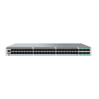
The SLX 9540 Switch has the following LEDs on the front panel:
• One power single-color status LED (green)
• One status bicolor status LED (green and amber)
• Two management single-color LEDs (green) for speed and link
• Four single-color status LEDs (green) for each of the 48 QSFP28 ports that indicate the status of the ports in 100 GbE mode,
2x50 GbE mode, 40 GbE mode, and 4x10 GbE mode
The
gure below shows the LEDs on the SLX 9540 Switch front panel.
ExtremeSwitching SLX 9540 Hardware Installation Guide
9036360-00 Rev AB 73

 Loading...


