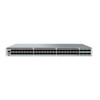
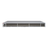
FIGURE 41 SLX 9540 Switch port-side LEDs
1. Management port link LED
2. Management port speed LED
3. Upper LEDs 0-3 for QSFP ports 49, 51, 53
4. Lower LEDs 0-3 for QSFP ports 50, 52, 54
5. SFP Port LEDs for ports 1-48
6. Status LED
7. Power LED
LED indications
The SLX 9540 Switch LED indicators are as follows:
• The Power/Status LEDs are visible to the front panel
• The Ethernet LEDs are integrated with the RJ45 connector
• The Power supply LEDs are integrated with the PSU
• The 10G and 100G Port LEDs are surface mount types. The are visible to the front panel
TABLE 13 SLX 9540 Switch LED
Indications
LED Function/state Meaning Possible cause
Power
O No power Some Power rails are dropping below
specication
Green Valid power. All monitored voltages are nominal
Status (bicolor)
Blinking Amber-Green Attention TBD by SW
Amber Fault/ initial state This LED shall be lit during the reboot
Green Board is operational
1G Ethernet Status
LED indications
ExtremeSwitching SLX 9540 Hardware Installation Guide
74 9036360-00 Rev AB

 Loading...


