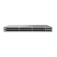
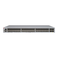
Identifying the airow direction
The power supply and fan assemblies are identied by the following airow directions:
• Intake power supply and fan assembly with an orange "I" label or without any label: Pulls air from the nonport-side of the
switch and exhausts it out the port side.
– Nonport-side air intake
– Port-side air exhaust
– Back-to-front (nonport-side to port-side) airow
– Part numbers ending with -R
• Exhaust power supply and fan assembly with a green "E" label: Pulls air from the port side of the switch and exhausts it out
the nonport-side.
– Nonport-side air exhaust
– Port-side air intake
– Front-to-back (port-side to nonport-side) airow
– Part numbers ending with -F
Times and items required
Installing or removing and replacing a fan assembly should require less than
ve minutes to complete.
The following items are required to replace a fan assembly:
• New fan assembly (must have the same airow direction as the fan assembly being replaced)
• #1 Phillips screwdriver
Replacing a fan assembly
When installing or replacing a fan assembly unit, keep in mind the following:
• Fan assemblies can be swapped in or out while the device is running. The remaining fan assemblies provide enough airow for
the device.
• The airow direction of the fan assembly must match that of the installed fan trays. All must be either exhaust or intake.
CAUTION
Ensure that the airow direction of the power supply unit matches that of the installed fan tray. The power supplies and fan
trays are clearly labeled with either a green arrow with an "E", or an orange arrow with an "I."
Inserting a new fan assembly
Use the following steps to install a fan assembly in the SLX 9540 switch.
Inserting a new fan assembly
ExtremeSwitching SLX 9540 Hardware Installation Guide
9036360-00 Rev AB 87

 Loading...


