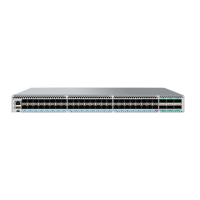
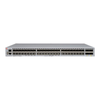
FIGURE 47 Connecting the grounding terminal
1. Grounding terminal
NOTE
The grounding lug must be sized according to NEC/CEC requirements. A typical installation would require:
1. Lug, copper, suitable wire size, #10 2-hole, 5/8" centers. For #10 ga. Wire, example lugs are:
• Panduit LCD10-10AF-L
• Pencom EL1244
• Hardware Specialties 912302
2. Screw, 10-32, ½", qty 2
3. Washer, #10, external locking, qty 2
Perform the following steps to connect to the grounding terminal.
1. Ensure that the rack in which the SLX 9540 device is mounted is properly grounded and in compliance with local regulations.
2. Ensure that there is a good electrical connection to the grounding point on the rack (no paint or isolating surface treatment).
3. Crimp the included grounding lug to a grounding wire of at least 12 American Wire Gauge (AWG). The 12 AWG wire and
grounding lug should be crimped together using a proper tool.
4. Attach the 12 AWG stranded copper wire to the grounding terminal on the SLX 9540 device using the screws included in the
grounding kit.
5. Attach the grounding wire to a grounding point.
NOTE
The terminal for the connection of a grounding conductor is not to be used with an aluminum conductor.
Grounding the SLX 9540 device
ExtremeSwitching SLX 9540 Hardware Installation Guide
84 9036360-00 Rev AB

 Loading...


