Quantum Series Videowall Processing Systems • Installation and Maintenance 33
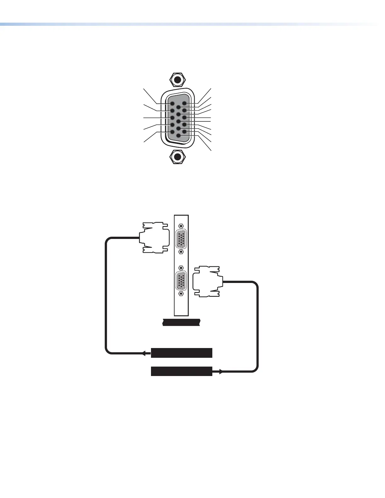
RGB/YUV connector pin assignments
The following diagram shows the pin assignments for the 15-pin high-density D-type
connectors on the RGB/YUV input card.
5 Gnd (H Sync)
10 Gnd (V Sync)
4 No Connection
9 DDC 5 V DC
3 Blue
8 Gnd (Blue Return)
2 Green
7 Gnd (Green Return
1 Red
6 Gnd (Red Return)
DDC Clock 15
V-sync 14
C-sync/H-sync 13
DDC Data 12
Gnd (DDC) 11
Figure 22. Pin Assignments for the RGB Connectors
RGB or component video connection example
The diagram below shows an example of RGB and component video sources connected
to the RGB/YUV input card.
10
IN
RGB / YPrPb Source
RGB / YPrPb Source
Figure 23. RGB/YUV Input Card Connection Example