Quantum Series Videowall Processing Systems • Installation and Maintenance 34
DVI input card (Quantum Elite only)
The DVI input cards are installed immediately to the left of the HDMI input cards in the
card frame. Connect one or two DVI-D video or graphics sources to the input connectors
on this card. The two DVI connectors are identical and can be used interchangeably. They
provide down-scaling of sources as required.
• Input connectors: The DVI input card contains two female 29-pin DVI-I connectors.
• Cables: DVI single or dual link video cables are recommended for this DVI
connection, 16 feet (5 meters) maximum. (Dual link signals are not supported.)
The Quantum Elite 615 model can accommodate up to 14 input cards, allowing a
maximum of 28 DVI video source inputs (two per card). The Quantum Elite 408 can
accommodate up to 7 input cards, allowing a maximum of 14 DVI video source inputs. If
more inputs are required, multiple card frames can be used.
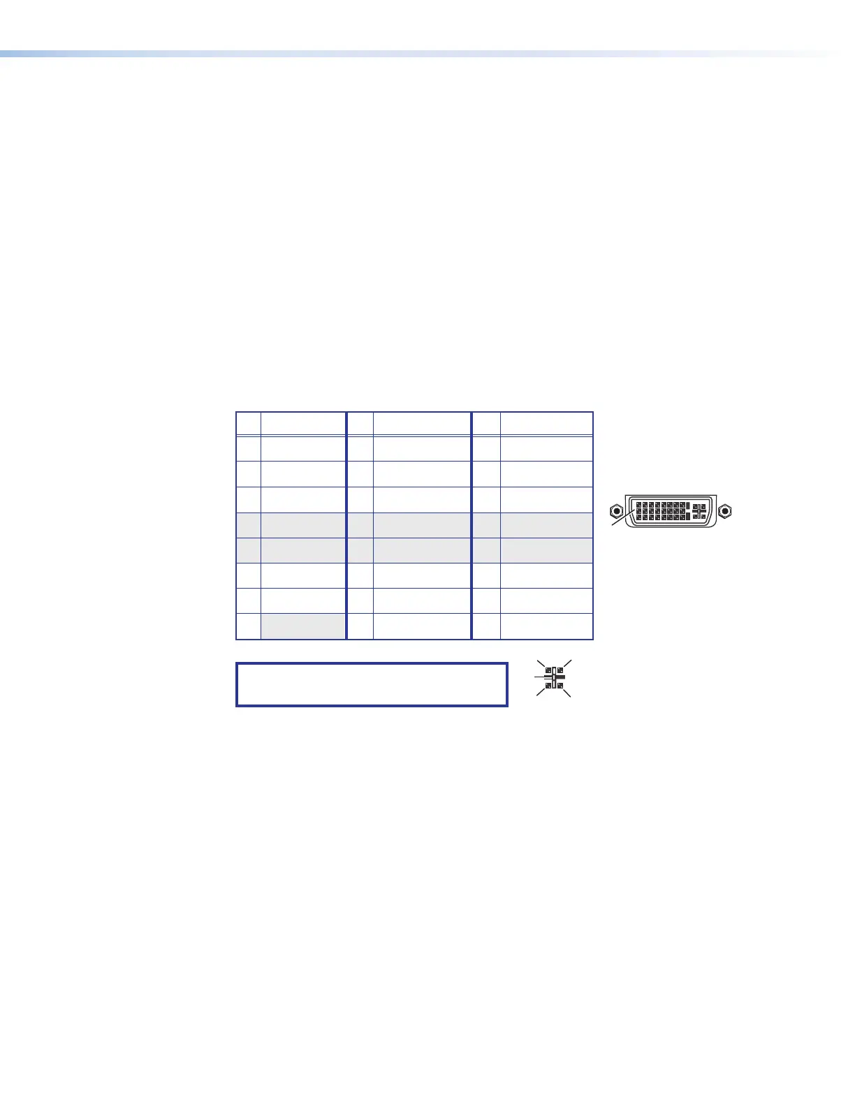
Connector pin assignments
The following diagram shows the pin assignments for the 29-pin DVI-I connectors on the
DVI input card.
8 Not used 16 Hot plug detect 24 TMDS clock–
Pin
Signal
Pin Signal
Pin
Signal
1 TMDS data 2– 9 TMDS data 1– 17 TMDS data 0–
2 TMDS data 2+ 10 TMDS data 1+ 18 TMDS data 0+
3 Ground (2/4) 11 Ground (1/3) 19 Ground (0/5)
4 Not used 12 Not used 20 Not used
5 Not used 13 Not used 21 Not used
6 DDC clock 14 +5 V power 22 Ground (clock)
7 DDC data 15 Ground (for 5 V) 23 TMDS clock+
1
8
17
24
9
Female DVI Connector
C1
C4
C2
C3
C5
NOTE: The analog pins (C1 through C5,
shown at right) are not enabled.
Figure 24. DVI Input Connector Pin Assignments