Quantum Series Videowall Processing Systems • Installation and Maintenance 40
LEDs on the HDMI output card
The HDMI output card contains two tri-color LEDs (one for each connector) that light to
indicate the HDMI output signal status and HDCP compliance:
Output LED Color Status Definition
Off Not defined in the output array
Red Not applicable
Green Unencrypted (non-compliant) HDMI or DVI signal
Amber HDCP encrypted (compliant) HDMI or DVI signal
Connecting a display to the output card
You can connect up to two display devices to an output card. The top connector is for
output channel 1; the bottom connector is for output channel 2.
The outputs can drive analog or digital display devices at a variety of resolutions (see the
Quantum Control Software User Guide to configure the display connections).
When connecting an analog display, you can use either a DVI-A type connector and cable
or the provided DVI-to-VGA adapter (to allow connection of a conventional 15-pin style
VGA cable).
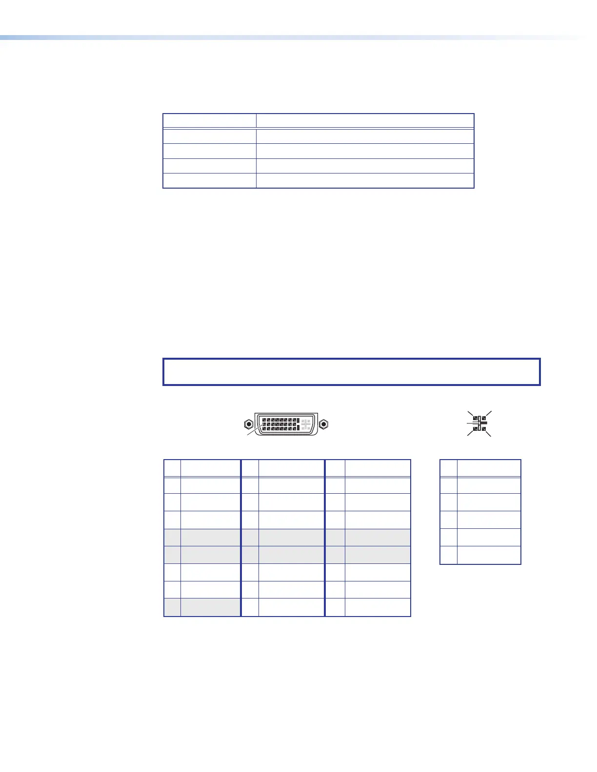
Output connector pin assignments
Figure 26 shows the pin assignments for the DVI output connectors.
NOTE: The pin assignments are the same for HDMI input and output connectors (see
HDMI connector pin assignments on page 36).
8 Not used 16 Hot plug detect 24 TMDS clock–
Pin
Signal
Pin Signal
Pin
Signal
1 TMDS data 2– 9 TMDS data 1– 17 TMDS data 0–
2 TMDS data 2+ 10 TMDS data 1+ 18 TMDS data 0+
3 Ground (2/4) 11 Ground (1/3) 19 Ground (0/5)
4 Not used 12 Not used 20 Not used
5 Not used 13 Not used 21 Not used
6 DDC clock 14 +5 V power 22 Ground (clock)
7 DDC data 15 Ground (for 5 V) 23 TMDS clock+
1
8
17
24
9
Female DVI Connector
C1
C4
C2
C3
C5
Digital Connections
Analog Connections
Pin
Function
C1
C2
C3
C4
C5
Red signal
Green signal
Blue signal
Horizontal sync
Ground
Analog Portion of DVI Connecto
Figure 29. DVI Output Connector Pin Assignments