version 4.7.2 – July 10th, 2022 Firmware version V2.1.7 and higher
EXXFIRE Installation and Service Manual 59
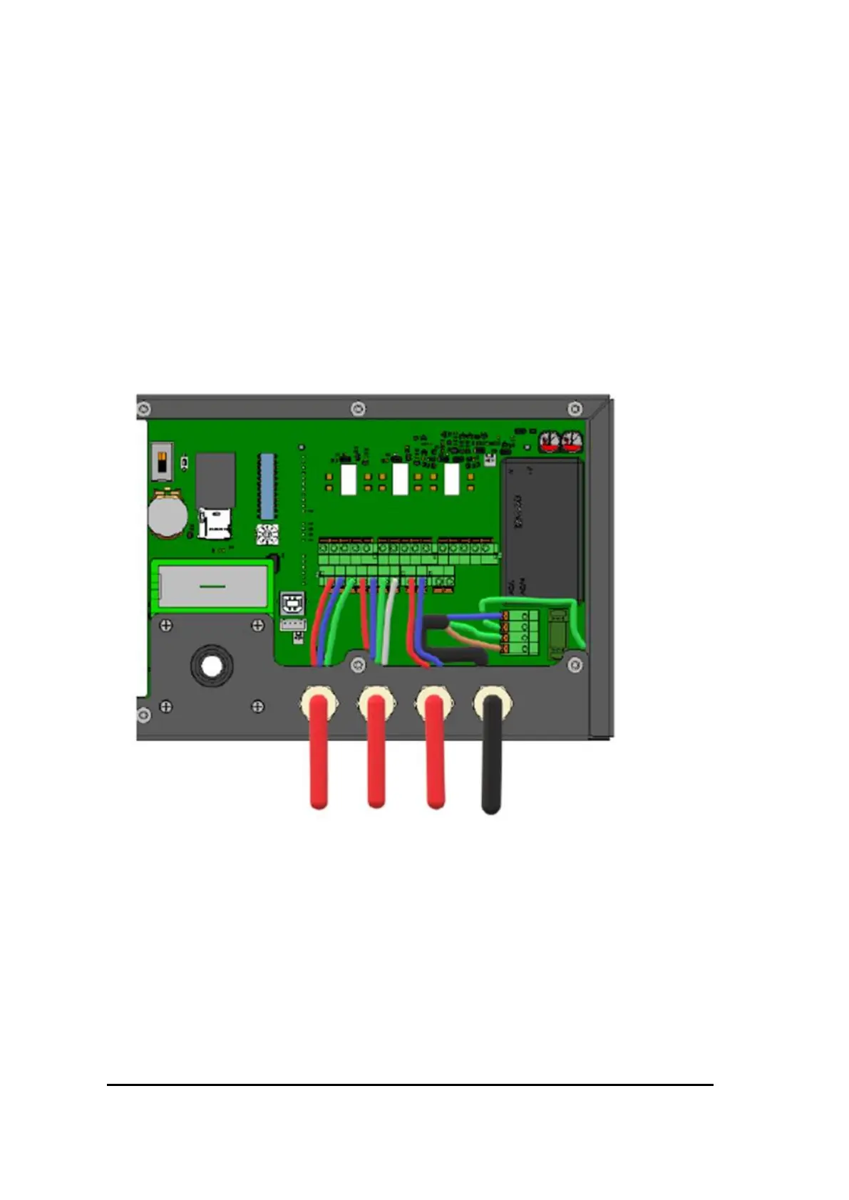
In a configuration where more than two systems are connected multiple cables must be used to
create a daisy chain connection of the systems. Each cable will connect two systems, whereby
each cable connects contacts RS485 A, RS485 B, GND and SHIELD of two systems. Figure 48
shows an example of an RS485 connection of a system in the middle of a daisy chain
configuration; this system has two cables connected to its RS485 connectors. The RS485
connection of the system at the left outer side of the daisy chain will typically look like Figure
47, having one cable to connect the RS485 bus to the adjacent system, whereby the shielding
of the cable is connected to the SHIELD contact. The system at the other outer side of the daisy
chain will look like Error! Reference source not found.;
Note that the shielding should be connected from both wires!
Figure 48 Wiring for connecting a system to two adjacent systems
The cables for the RS485 connections must be terminated at the outer two systems of the daisy
chain configuration only. This can be done using the DIP switch “T”, as explained in section 5.
Choose the most appropriate cable glands for the RS485 cable(s) to be used.
Strip an appropriate amount of the outer sheath away and strip the conductors before inserting
into the cable gland. Ensure that the gland seals tightly against the outer sheathing, providing
both physical support for the cable, and an airtight seal. Failure to do this will result in
increased false alarms since the sampled air flow rate will be less stable.