MPC-6000 / MPC-7000 / RND-2 INSTALLATION, OPERATION AND MAINTENANCE MANUAL
39
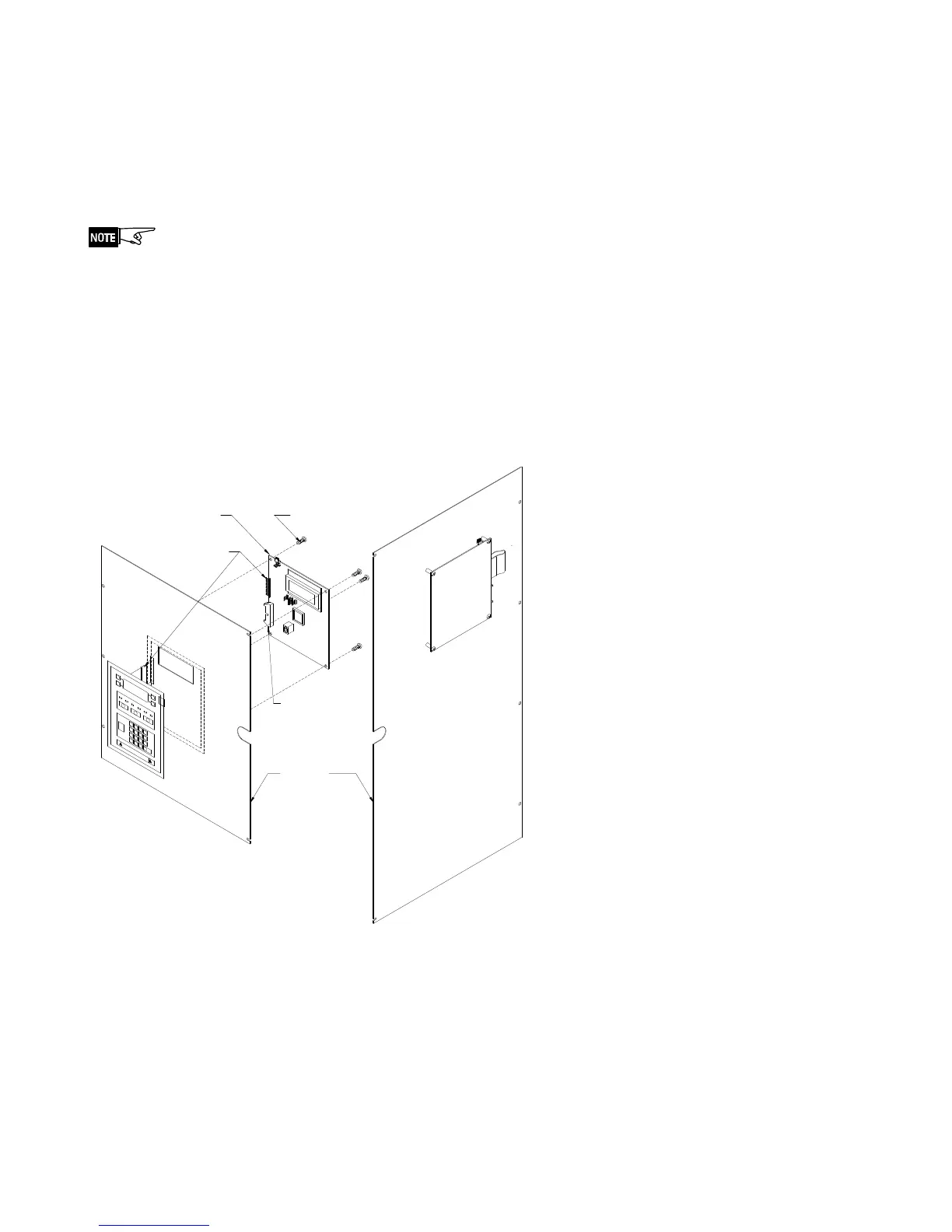
Display Board Installation –
P/N MPC(6/7)-DB, MPC6-DB2, RND2-DB or RN2-DB2
With the Inner Front Plate closed, carefully pass connector and cable from keypad through
vertical slot in front plate.
Remove backing from keypad and carefully attach keypad to front plate. Center window in
keypad on large opening in front plate.
Do not remove the small strip of paper backing next to the ribbon cable. This will
prevent the cable from adhering to the keypad prior to positioning on the plate.
Attach the cable connection from the keypad on the Inner Front Plate to connector J3 on
the Display Board (P/N MPC(6/7)-DB, MPC6-DB2, RND2-DB or RND2-DB2).
Secure Display Board (P/N MPC(6/7)-DB, MPC6-DB2, RND2-DB or RND2-DB2) to Inner
Front Plate Assembly using four of the provided #6-32x1/4” screws (P/N 906-220604).
Plug the Cable Assembly (P/N 555-446055) into connector J1 of the Display Board
(P/N MPC(6/7)-DB, MPC6-DB2, RND2-DB or RND2-DB2) and to connector J11 of the
Main Board (P/N MPC6-MB, MPC6-MB2 or MPC7-MB).
PLATE
906-220604 (4)
#6-32 x 1/4 SCREW
MPC-6000
ASS'Y
J3 - Keypad
Connection
Board
Display
to Main
J1 - Connection
Board
Termination
MPC-7000
showing Display
Board and Keyboard
to Front Plate Ass'y
Board attached
showing Display
being attached
to Front Plate Ass'y