4
SETUP
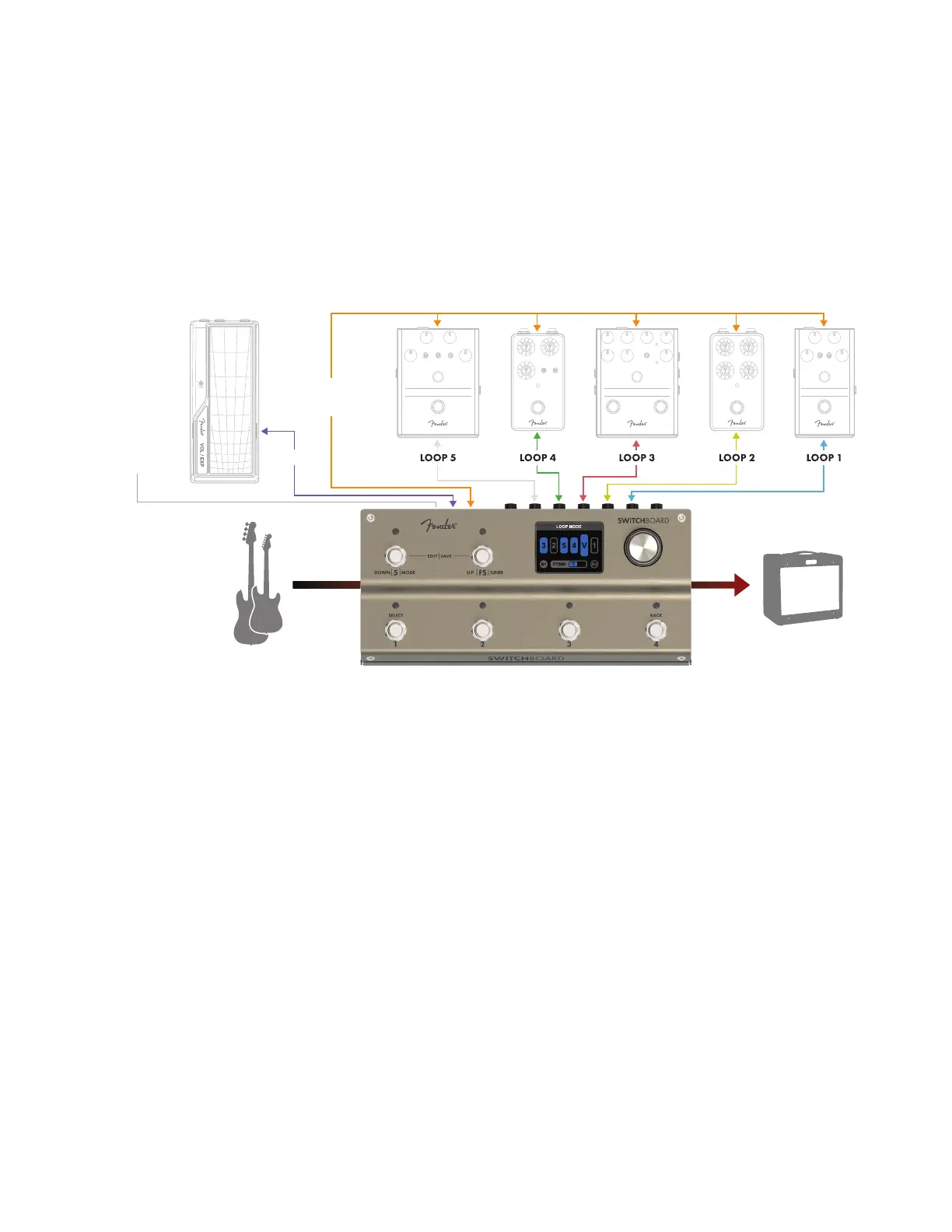
To setup Switchboard, organize your pedals into ve groups and assign each of these to one of the ve num-
bered rear-panel SEND/RETURN jack pairs, referred to from right to left as loops 1 through 5. Ten patch cables are
needed to connect all ve loops to Switchboard. For stereo operation, Loop 5 requires the left and right signals
to be converted into TRS patch cable (left tip/right ring) going into the Loop 5 RETURN jack.
For more advanced control, Switchboard can send footswitch control to an amp, send MIDI messages to
external gear, and control the internal volume pedal using a TRS expression pedal. The rear-panel FTSW jack
is compatible with amps and pedals that can operate with a TRS (double footswitch) or TS (single footswitch)
ground-shorting pedal (refer to your amplier’s manual for compatibility).
SETUP TIPS
• PHYSICAL PLACEMENT: For easy access to its input and output, placing Switchboard at lower right on a pedalboard is
recommended.
• SIGNAL PATH PLACEMENT: Place Switchboard as close to the beginning of your signal path as possible to make full use
of its onboard tuner, internal volume pedal and high-quality buers. Note that Switchboard’s internal buers can
be turned o for use with impedance-sensitive pedals (such as a vintage fuzz) in one of the loops.
• GROUPING LOOPS 1-4: Loops 1 through 4 can be rearranged in any order quickly and easily. Consider how your pedals
physically t on your pedalboard when assigning them to loop numbers—for example, you may want to place reverb
near the end of the signal path, but the pedal may t best on your board closest to the loop 1 SEND and RETURN jacks.
To minimize cable runs and maximize pedalboard space, use loop 1 for reverb and rearrange Switchboard’s internal loop
order to place loop 1 near the end of the signal path.
• LOOP 5: Loop 5 is stereo enabled, oering the ability to send output from stereo eects (a ping-pong delay, for
example) to a stereo input or two ampliers. To enable stereo output, switch the rear-panel STEREO SELECTION
SWITCH to STEREO. Note that Loop 5 can only send a stereo signal when it is in the last position in the signal path;
placing any other loop or the volume pedal after Loop 5 in the signal path will defeat the stereo eect and result
in a summed mono signal being sent to both left (tip) and right (ring) Switchboard outputs.
• PATCH CABLES: Straight-ended patch cables are recommended to connect eect loops to Switchboard, minimizing
cable overlap and rear-panel interference.
FTSW
CONNECT TO AMP
OR PEDAL
FOOTSWITCH JACK
EXP PEDAL
MIDI PC/CC
COMMANDS