7
LOOP MODE
LOOP MODE delivers performance-focused real-time pedalboard control and is ideal for creating presets. It
oers straightforward manual on/o control of the ve eects loops, footswitch control of the rear-panel FTSW
jack and control of the internal volume pedal using the rear-panel EXP jack and an external expression pedal.
LOOP MODE controls the footswitches in real time, consequently locking the ENCODER’s scroll and press
functions to prevent accidental changes. LOOP MODE parameters such as loop order and buer status are
easily edited using the LOOP MODE EDITOR.
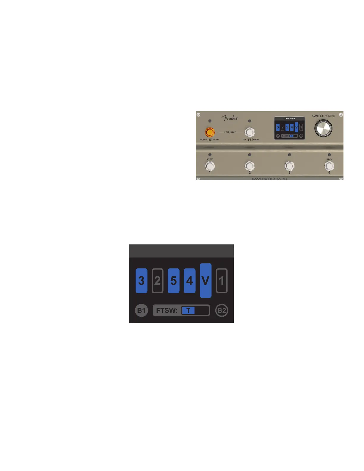
ENTERING LOOP MODE
Press and hold Footswitch 5 for one second to enter
LOOP MODE from any other mode. When doing so, pa-
rameters set in the last LOOP MODE session are loaded.
The LOOP MODE screen displays four types of symbols
that quickly and easily indicate control function status
and position: Loop symbols (ve), the Volume Pedal sym-
bol, Buer symbols B1 and B2, and the FTSW symbol.
LOOP MODE SCREEN
The LOOP MODE screen displays the signal path graphic, buer icons and FTSW icon to indicate current status
of all loops, buers, internal volume pedal and the FTSW jack. The status and order of each eects loop is indi-
cated by its loop icon, which changes as a loop is turned on and o.
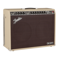
LOOP ICONS: The ve loop symbols indicate the placement order of each eect loop and its on/o status. Loop
icons are numbered 1-5 to correspond to the footswtiches and SEND and RETURN jack pairs; the corresponding
footswitch is used to toggle that eects loop on or o regardless of the loop’s location in the signal path.
INTERNAL VOLUME PEDAL ICON: The larger Volume Pedal symbol (V) indicates the signal path placement
and on/o status of the internal volume pedal.
BUFFER ICONS: The circular B1 and B2 symbols in the lower corners indicate on/o status of the input (B1)
and output (B2) buers. Because they can’t be toggled on and o with a footswitch, their status is indicated
using a solid-gray symbol (ON) or a gray-outlined symbol (OFF).
FTSW FOOTSWITCH ICON: The FTSW symbol at bottom center displays the on/o status of the rear-panel
FTSW conductors controlled by Footswitch FS. The box indicates the conductors being controlled—T (tip) and
R (ring)—and turns blue when the FTSW output is active.
LOOP MODE
LOOP MODE
Inactive output buer B2 (outlined)
Active input buer B1 (gray)
Active footswitch in tip (T) conguration (blue)
Active volume pedal (V) in position 5
Active loop icons (blue)
(loop 3 in position 1, loops 5
and 4 in positions 3 and 4)
Inactive loop icons (outlined) (loop
2 in position 2, loop 1 in position 6)