42
General standards
The electric wiring must be installed by qualified personnel according to the standards that are in force at the time of installation in the destination
country. Before beginning any work on the electrical system, first make sure that the unit's power supply line is isolated at the source.
N.B.: Refer to the wiring diagram attached to the unit.
Connection to mains power
The units have been completely wired in the factory and prepared for connection to the power supply line. The electrical board is protected by an
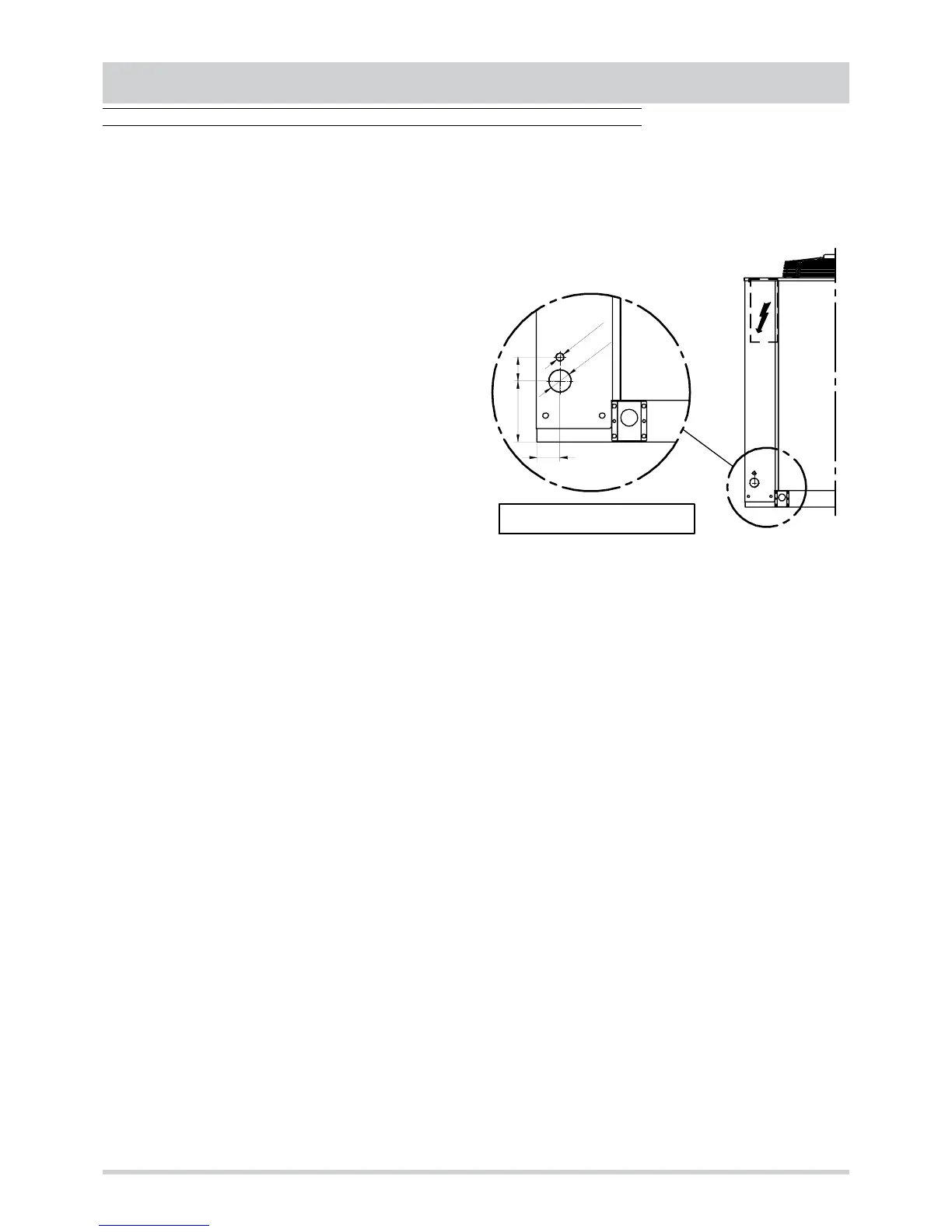
CONNECTIONS
Q.E.
* = FORI PRETRANCIATI
61
261 36
O
5
8
*
O
2
0
*
DETAILS
external panel that can be removed by means of rotating a wrench for
screws by _ turn and can be inspected by means of the general cutoff
switch's door blocking mechanism.
Power supply system
The power cables of the machine's power supply line must be selected
by a symmetrical 3 phase voltages system equipped with a neutral wire
and separate protective ground conductor.
V = 400 V ± 10%
f = 50 Hz
The power cables must enter the unit through the precut holes located
in the lower part of the support. These holes must be protected with the
use of bushings of an adequate size, and it is advisable to anchor the
cables firmly to the machine’s structure.
The cable terminals must enter the electrical board’s box through the
existing holes located in the lower part of the box, and must be attached
to the terminals of the general cutoff switch located inside the electrical
board.The neutral wire included in the line must be connected to the
neutral terminal marked “N” corresponding to the fourth pin of the
general cutoff switch. The protective conductor, originating from the
power supply line, must be connected directly to the ground screw
marked “PE” so as to guarantee the equipotential connections of all the
metal masses and the structural components of the machine.
IMPORTANT
The connection cables must have a cross-section that is suitable for
the unit’s power input and must be of a size that is in compliance with
current regulations.
The electronic data provided in the technical documentation refer to the standard unit without accessories. To select the size of the power supply
line always refer to the FLI and FLA values listed on the data plate, which can also be calculated from the input values of the standard units, taking
into consideration all the nonstandard accessories and components that have been installed.
Upline protection
Before the above mentioned line it is necessary to install an automatic switch that is suitable for providing over-current protection and protection
against indirect contacts.
The coordination between the line and switch must be executed in compliance with current regulations on electrical safety with regard to the type
of installation and the environmental conditions of the installation.
Connections that are the user’s responsibility
ll’interno del quadro elettrico è prevista una morsettiera (XU) dedicata ai seguenti collegamenti:
General alarm
Contact free of voltage. Maximum voltage at the terminal ends: 24V. Maximum current: 5A.
Contact open: alarm not activated.
Contact closed: alarm activated.
On-off remote
It is possible to connect a remote device for turning the unit on and off (selector switch, clock controller, centralized monitoring device, etc.) that is
equipped with a contact that is free of voltage and that is suitable for switching extremely low power loads.
Contact open: unit is turned off (OFF).
Contact closed: unit is turned on (ON).
The bridge between the terminals, which was installed at the factory, must be removed if remote control is used.
Remote summer-winter
It is possible to remotely switch between cooling mode operation and heating mode operation by connecting a device equipped with a contact that
is free of voltage and that is suitable for switching extremely low power loads.
Contact open: heating mode operation.
Contact closed: cooling mode operation.
The bridge between the terminals is not necessary, because this function must be activated by means of a parameter (refer to Control section). If
this function is used, it will no longer be possible to switch the operating mode by means of the keyboard.
Economizer
It is possible to translate the set point (both in cooling mode and in heating mode) by means of a device equipped with a contact that is free of
voltage and that is suitable for switching extremely low power loads (refer to the Regulation section for further details).
Contact open: set point translated.
Contact closed: set point unchanged.
The bridge between the terminals, which was installed at the factory, must be removed if this function is used.
Forcing damper open
It is possible to force open the outside air damper by means of a device equipped with a contact that is free of voltage and that is suitable for
switching extremely low power loads.
Contact open: damper open.
Contact closed: damper closed.
The bridge between the terminals, which was installed at the factory, must be removed if this function is used.
Remote thermostat or keyboard
It is possible to connect devices (accessories) to the unit that replicate the commands that are available on board the machine (see Control section
for further details).
PRECUT HOLES