54
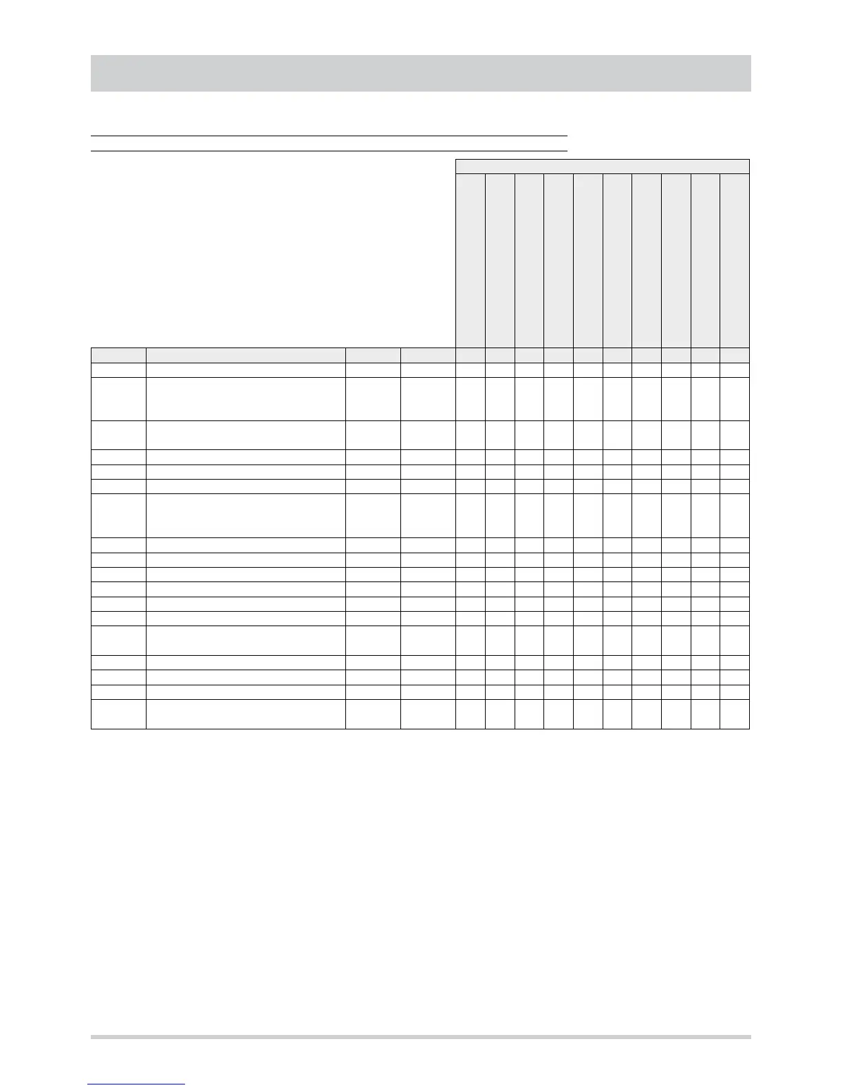
CONTROL SYSTEM
Loads BLOCKED
Compressor circuit 1
Compressor circuit 2
Reverse cycle valve circuit 1
Reverse cycle valve circuit 2
Internal fan - Return air fan
Electrical heater coil
Gas heating module
Hot water coil 3 way valve
External fans circuit 1
External fans circuit 2
Outdoor air damper
CODE ALARM
RESET
(1)
RL2 RL1 RL2 RL3 RL4 RL5 RL6 RL7 TC1 TC2 AN3
E00 Remote ON-OFF A ID10 x x x x x x x x
E01
High pressure circuit 1Compressor ther-
mal cut-out circuit 1External fans thermal
cut-out circuit 1
M ID1 x
E02 Low pressure circuit 1Sequence meter AS (3) ID2 x x
E05 Outlet air low temperature AS (3) (2) AI2 x x x x
E06 Outlet air temperature probe fault A AI2 x x x x x x x
E07 Fluid probe fault circuit 1 A AI3 x x x x x x
E21
High pressure circuit 2Compressor ther-
mal cut-out circuit 2External fans thermal
cut-out circuit 2
M ID3 x x
E22 Low pressure circuit 2 AS (3) ID4 x x
E26 CO2 probe fault A AI5 x x x x x x x x
E27 Fluid probe fault circuit 2 A AI6 x x x x x
E40 Inlet air temperature probe fault A AI1 x x x x x x x x
E41 Filters differential pressure switch M ID6 x x x x x x x x
E42 Outside air temperature probe fault A AI4 x x x x x x x x
E43
Internal fan thermal cut-out Inlet fan ther-
mal cut-out
M ID5 x x x x x
E46 Inlet air high temperature A AI1 x x x x x x
E48 Inlet air humidity probe fault A AI7
E49 Outside air humidity probe fault A AI8
E63
Heaters thermal cut-outGas-fired heating
module alarm
M ID7 x
Alarm table
(1) A = automatic reset , M = manual reset , AS (x) = automatic until reaching x events per hour, then manual
(2) Manual reset can also be carried out by means of remote On-Off (ID10) or remote Cooling-Heating (ID11)