49
CONTROL SYSTEM
Control system
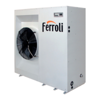
The unit is managed by a controller with microprocessor consisting of a card, inside the electrical panel, to which all the loads and
control devices are connected and a user interface accessed by removing the electrical panel protection panel. A further interface
can be connected to the card for remote control of the machine.
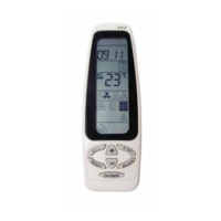
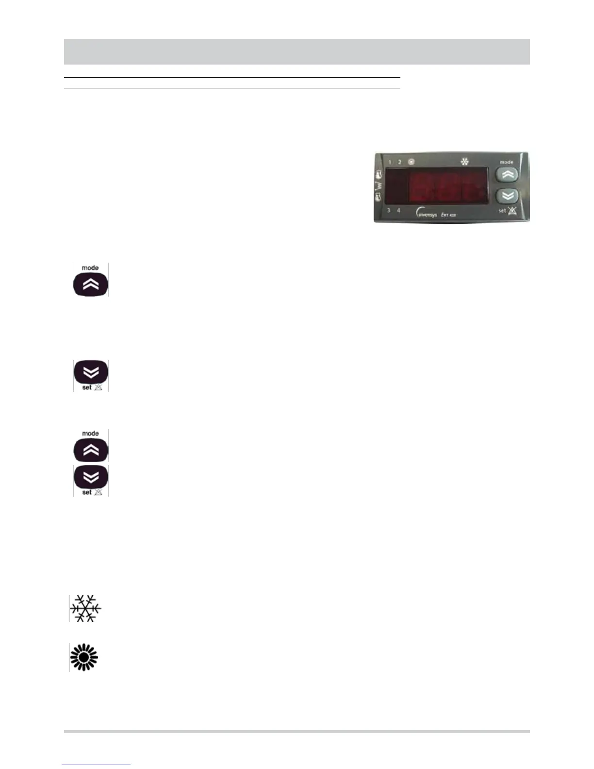
Standard user interface
All the units are supplied with a standard interface (EKP400 RT type keyboard)
equipped with two buttons and a display (3-digit with sign and decimal point + 7
LEDs) through which it is possible to :
• display and modify the operating parameters of the unit
• display the analogue and digital inputs
• set the operating mode
Mode button
Used to select the operating mode if the “remote Cooling-Heating" control is not used and the “remote Thermostat”
accessory is not connected (EKF400 RT type keyboard).
Pressing the button gives the following sequence:
Standby à Cooling à Heating à Standby
Heating mode is only present for units with heat pump.
In menu mode the button is used to scroll the menu up or to increase the value of the parameter selected.
Set button
Press once to reset all the manual-reset alarms no longer active.
Keep the button pressed for 2 seconds to display the set point of the set operating mode. The value can be modified
(with the “mode” and “set” buttons) and saved (by pressing both buttons at the same time or when the display of
set point disappears for time-out).
In menu mode the button is used to scroll the menu down or to decrease the value of the parameter selected.
Mode button + set button
Press and release both buttons within 2 seconds to go down one level on the menu. Keep both buttons pressed for
more than 2 seconds to go up one level. If the last level of a menu is being displayed, pressing and releasing within
2 seconds will make it go up one level in any case.
Display
The following are shown in normal display :
• the temperature adjustment, or the inlet air temperature (in tenths of degrees Celsius with decimal point or in degrees
Fahrenheit without decimal point)
• the alarm code, if at least one of them is active (if several alarms are active the code of the first one according to the Table
of Alarms is displayed)
In the menu mode, the display depends on the position (see menu structure).
COOLING mode LED
ON unit in Cooling mode
HEATING mode LED
ON unit in Heating mode
If the Cooling LED and Heating LED are not lit the unit is on STANDBY.