50
CONTROL SYSTEM
LED step 1 : compressor circuit 1
ON : compressor circuit 1 on
OFF : compressor circuit 1 off
FLASHING at a frequency of 1 Hz (1 per second) : timing in progress
FLASHING at low frequency (< 1 Hz) : defrost in progress on circuit 1
Led step 3 : compressor circuit 2
ON : compressor circuit 2 on
OFF : compressor circuit 2 off
FLASHING at a frequency of 1 Hz (1 per second) : timing in progress
FLASHING at low frequency (< 1 Hz) : defrost in progress on circuit 2
Heating elements / gas heating module LED
ON : heaters on / gas heating module on
OFF : heaters off / gas heating module off
The LEDs of step 2 and step 4 are not used.
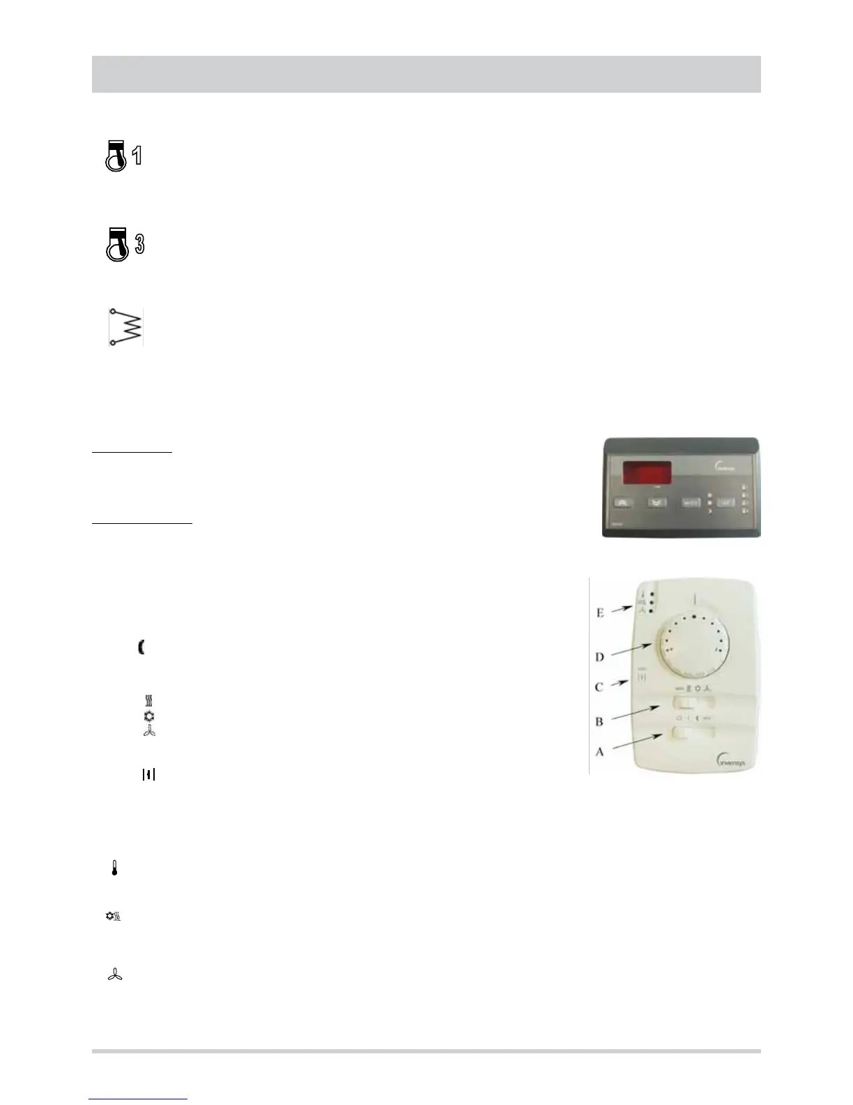
Accessories user interfaces
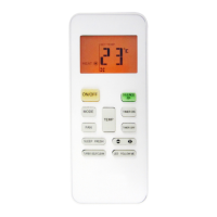
Remote control
This is the standard wall-mounted interface version. The only difference is the presence of 4
buttons : in addition to the mode and set buttons, up and down buttons are available for scrolling
the menus and increasing or decreasing the value of the parameter selected.
Remote thermostat
This is a simplified wall-mounted interface used to :
• set the operating mode
• set a deviation with respect to the set point
• display the operating status and the presence of active alarms
The selector A is used to set the device to one of the 4 possible states :
0 standby
I ON
night purging
eco Economy mode
The selector B is used to set the device to one of the 4 possible operating modes :
auto automatic mode
heating mode
cooling mode
ventilation mode
The selector C is used to define the outside air shutter opening mode :
auto automatic adjustment by the controller
shutter completely open
The knob D is used to set a deviation with respect to the set point of the operating mode selected. The deviation is algebraically
added to the active set point and its max. value (from the midpoint to each stop) is ± 5°C.
The status LEDs E indicate respectively :
off adjustment resources off
green adjustment resources active
off standby
green cooling
red heating
off inside fan off
green inside fan active
red alarm status