55
CONTROL SYSTEM
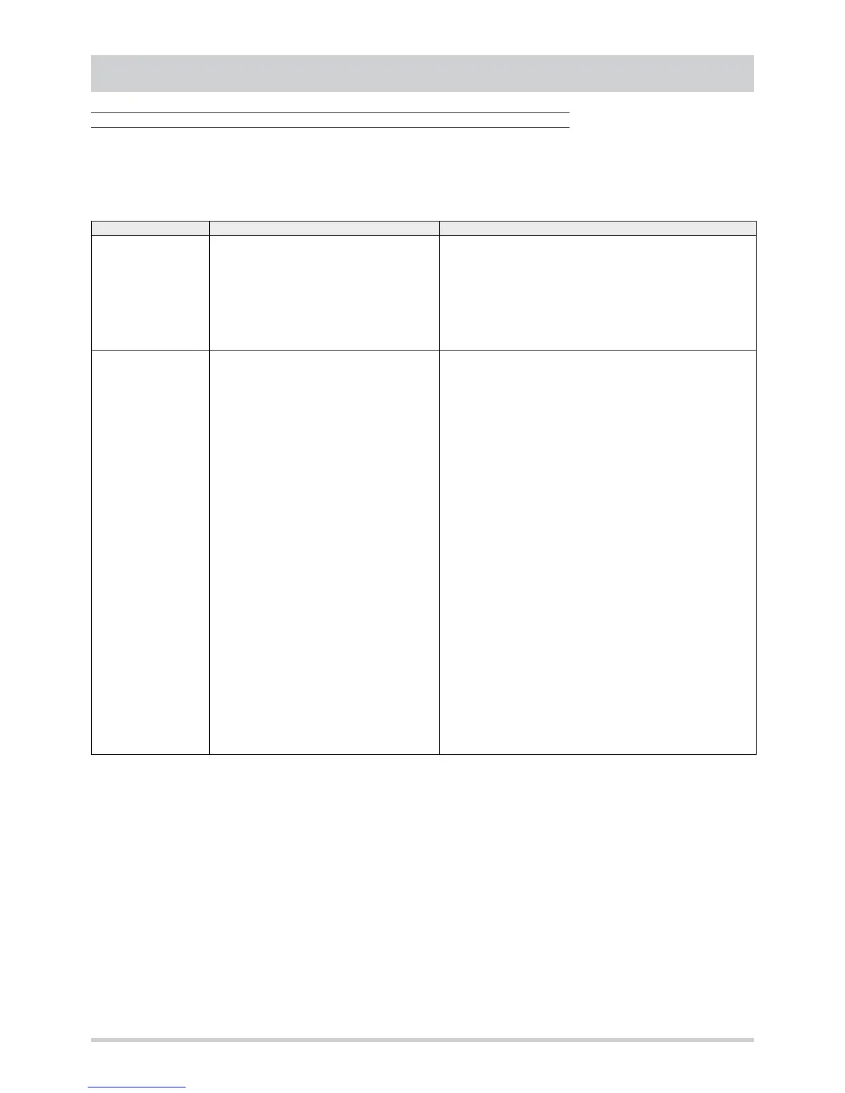
Alarm diagnostics
Intervention of a safety device indicates an operation fault. Before resetting the alarm it is necessary to carry out a check and
eliminate the cause of the alarm.
Given below is a list of possible problems and causes, as a troubleshooting guide for some faults that could occur in the unit. The
list does not cover all possible faults.
ALARM CAUSE POSSIBLE ACTION OR CHECK
E00
remote ON-OFF
1. remote ON-OFF digital input open.
2. No bridge between the remote ON-OFF control
digital input terminals.
1. If using the remote ON-OFF control, close the selector connected to
the corresponding digital input or check the programmer clock set-
tings.
2. If not using the remote ON-OFF control, insert a jumper between the
terminals of the corresponding digital input.
Remember to check the electrical connections at the remote ON-OFF
control input terminals. A faulty or loose connection, even if seeming
correct, can trigger the alarm.
E01
High pressure circuit 1
Compressor thermal cut-
out circuit 1
External fans thermal
cut-out circuit 1
E21
High pressure circuit 2
Compressor thermal cut-
out circuit 2
External fans thermal
cut-out circuit 2
1. Pressure switch fault or not correctly set.
2. Presence of non-condensable substances in the
refrigerant circuit. The symptoms are :
- poor refrigerating capacity
- excessive difference between the air temperatu-
re and the dew point (over 20°C)
- high evaporation pressure
- high subcooling
- presence of bubbles on the fluid indicator
3. Excessive refrigerant charge. The symptoms
are:
- high evaporation pressure
- high subcooling
- high condensation pressure
4. Finned coils clogged or dirty.
5. Operating temperature outside the operating li-
mits provided for.
6. Treated air flow excessive (in cooling) or insuffi-
cient (in heating).
7. Unit not correctly installed.
8. External fans faulty.
9. External fan speed adjustment system ineffi-
cient.
1. With a pressure gauge on the pressure point provided on the com-
pressor delivery piping, check the pressure switch intervention setting
value and the reset value.
2. Carry out refrigerant recovery, vacuum and charge.
3. Reduce the refrigerant charge
4. Remove the dirt and any obstructions covering the pipes and fins of
the coils and that prevent correct heat exchange.
5. Make sure the temperatures of the outside air and the treated air are
within the unit's operating limits.
6. Make sure the treated air flow is between the max. and min. values
provided for. Make sure the inlet and outlet ducts are open and free
of obstructions. Check the state of the filters for the treated air. Check
the setting of the internal fan transmission and belt tension.
7. Make sure the unit is installed respecting the minimum required ope-
rating spaces. Make sure the external coil is not exposed to direct
sunlight, no hot air is directed towards the coil, and that there is no
recirculation of air expelled by the fans.
8. Check for any obstructions on the fan blades. Check the electrical
windings and replace any damaged fans.
9. Check the ventilation control PCBs and replace them if necessary.
Check the positioning of the fluid probes and their integrity. Check the
ventilation parameters.
A quick test for checking the presence of incondensables in the refri-
gerant circuit consists of comparing the saturated dew point (measured
with a pressure gauge on the high pressure point) with the ambient tem-
perature, with the unit stopped and after the temperature of the refrige-
rant fluid has had time to balance itself with the temperature of the air
surrounding the condenser. If the temperature indicated by the pressure
gauge exceeds the measured ambient temperature by 2°C this means
there are traces of incondensables in the circuit. The greater the differen-
ce in temperature, the greater the quantity of incondensables present.