52
CONTROL SYSTEM
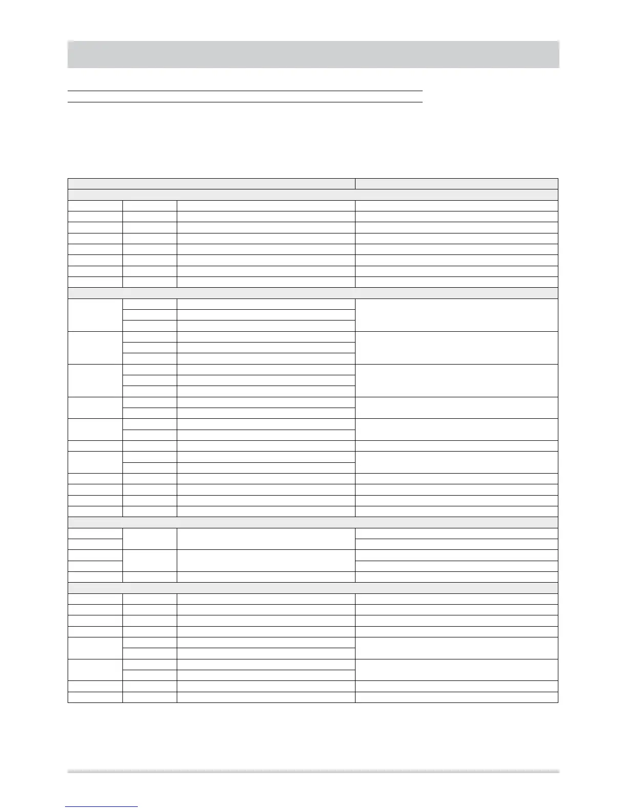
Inputs and outputs
To monitor the unit, the controller is equipped with the following inputs and outputs :
• Analogue inputs : 8
• Digital inputs : 11
• Analogue outputs : 3
• Digital outputs : 8
DESCRIPTION CHARACTERISTICS
Analogue inputs
AI1 STR Ts.b. probe inlet air NTC temperature sensor (-30°C ¸ 90°C)
AI2 STM Ts.b. probe outlet air NTC temperature sensor (-30°C ¸ 90°C)
AI3 SL1 fluid probe circuit 1 NTC temperature sensor (-30°C ¸ 90°C)
AI4 STE Ts.b. probe outside air NTC temperature sensor (-30°C ¸ 90°C)
AI5 CO2 CO2 probe live input : 0 ¸ 5 Vdc
AI6 SL2 fluid probe circuit 2 NTC temperature sensor (-30°C ¸ 90°C)
AI7 SUR inlet air humidity probe input current : 4 ¸ 20 mA
AI8 SUE outside air humidity probe input current : 4 ¸ 20 mA
Digital inputs
ID1
PA1 High pressure switch circuit 1
voltage free digital inputTCP1 Compressor thermal cut-out 1
TVE1 External fans thermal cut-out circuit 1
ID2
PB1F Low pressure switch circuit 1 - cooling
voltage-free digital inputPB1C Low pressure switch circuit 1 - heating
SEQ Sequence meter
ID3
PA2 High pressure switch circuit 2
voltage-free digital inputTCP2 Compressor thermal cut-out 2
TVE2 External fans thermal cut-out circuit 2
ID4
PB2F Low pressure switch circuit 2 - cooling
voltage-free digital input
PB2C Low pressure switch circuit 2 - heating
ID5
TVI Internal fan thermal cut-out
voltage-free digital input
TVR Inlet fan thermal cut-out
ID6 PDF Filters differential pressure switch voltage-free digital input
ID7
TBRE Heaters thermal cut-out
voltage-free digital input
AMTG Gas-fired heating module alarm
ID8 ECO Economy mode voltage-free digital input
ID9 EF Shutter forced opening voltage-free digital input
ID10 ON-OFF Remote On-Off voltage-free digital input
ID11 E-I Remote Cooling- Heating voltage-free digital input
Analogue outputs
TC1
VE1 External fans circuit 1
output for external module (PWM)
AN1 output for external module (0 ÷ 10 Vdc)
TC2
VE2 External fans circuit 2
output for external module (PWM)
AN2 output for external module (0 ÷ 10 Vdc)
AN3 SR Outside air shutter voltage output : 0 ÷ 10 Vdc
Digital outputs
RL1 CP1 compressor circuit 1 relays 5 A resistive 230V~ (1/4 hp 230V~; 1/8 hp 125V~)
RL2 CP2 compressor circuit 2 relays 5 A resistive 230V~ (1/4 hp 230V~; 1/8 hp 125V~)
RL3 VIC1 Reverse cycle valve circuit 1 relays 5 A resistive 230V~ (1/4 hp 230V~; 1/8 hp 125V~)
RL4 VIC2 Reverse cycle valve circuit 2 relays 5 A resistive 230V~ (1/4 hp 230V~; 1/8 hp 125V~)
RL5
VI Internal fan
relays 5 A resistive 230V~ (1/4 hp 230V~; 1/8 hp 125V~)
VR Inlet fan
RL6
BRE Heaters
relays 5 A resistive 230V~ (1/4 hp 230V~; 1/8 hp 125V~)
MTG Gas-fired heating module
RL7 V3W Hot water 3-way valve relays 5 A resistive 230V~ (1/4 hp 230V~; 1/8 hp 125V~)
RL8 ALL Alarm relays 5 A resistive 230V~ (1/4 hp 230V~; 1/8 hp 125V~)