7
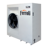
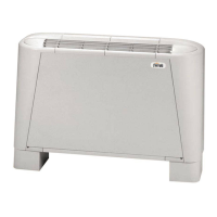
GENERAL FEATURES
The internal side heat exchanger (user side) (2) is a finned
coil realized with grooved copper pipes and aluminium fins
with notched profile to increase the heat exchange coefficient.
To avoid condensate drag, the frontal crossing air velocity
don't exceed 2,7 m/s, also with the maximum air flow rate
configuration and in the least favourable thermohygrometric
conditions. For the condensate drainage there is a stainless
steel drain tray with inclined bottom, equipped with threaded
connector for the discharge.
The external side heat exchanger (source side) (3) is a
finned coil realized with grooved copper pipes and aluminium
fins with notched profile.
The expansion device (4), a thermostatic expansion valve with
external equalizer , allow the unit to adjust itself to the different
operating conditions keeping steady the set superheating.
The presence in each refrigerant circuit of two valves (one
for the cooling mode and one for the heating mode) allow
to optimize the adjustment of each valve and to obtain the
maximum efficiency.
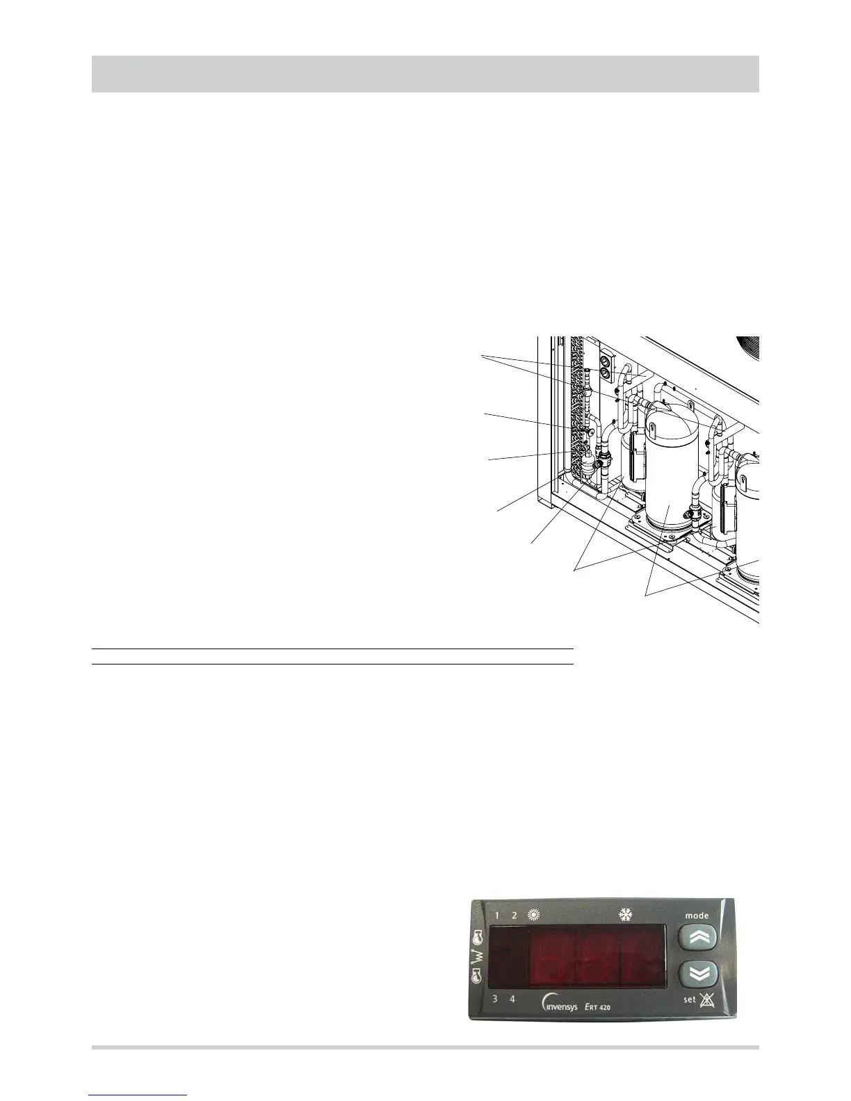
Each refrigerant circuit contains moreover solid core hermetic
filter dryer (5) to restrain impurity and moisture residuals that
could be present in the circuit, liquid separator (6) placed on
the inlet pipe to protect the compressor against liquid returns,
liquid and humidity indicator (7) to detect the presence of
liquid before each thermostatic valve and allow to verify the
presence of humidity inside the refrigerant, shut off valves
(8) upstream and downstream of each external coil to allow to
stock all the refrigerant inside the coils (pump down) and permit
to execute maintenance operations on the refrigerant circuit
without discharging it, high and low pressure switches in
order to assure the compressor to operate inside the permitted
limits, 4 way reverse cycle valve (9) to allow operating
mode change reversing the refrigerant flow (only heat pump
models) and pressure connections SAE 5/16” - UNF 1/2” -
20 equipped with pin, gasket and blind nut, as required for the
use of R410A refrigerant (they allow the complete check of
the refrigerant circuit: compressor inlet pressure, compressor
outlet pressure and thermostatic valve upstream pressure).
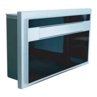
Electrical panel. It contains all the power, control and security
components necessary to guarantee the unit to work properly.
The unit is managed by a microprocessor controller to which all
the electrical loads and the control devices are connected. The
user interface, accessible removing the protection panel of the
electrical board, allow to view and to modify, if necessary, all
the parameters of the unit.
All the units are supplied with an outdoor temperature sensor,
already installed on the unit.
Control system
The unit is managed by a microprocessor controller to which,
through a board placed inside the electrical panel, all the
electrical loads and the control devices are connected. The
user interface, accessible removing the protection panel of
the electrical board, is realized by a display and two buttons
that allow to view and, if necessary, modify all the operating
parameters of the unit.
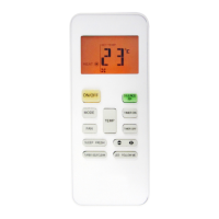
Are available, as accessories, a remote control, that reports all
the functionalities of the user interface placed on the unit, or a
remote thermostat.
The main functions available are :
- treated air temperature management (through set point
adjustment)
- treated air humidity management (only with enthalpic free
cooling option)
- treated air quality management (CO
2
)
- thermal or enthalpic (option) free cooling
- external fan management by means of continuos rotational
speed control (option)
- internal fan management
- return air fan management
- integrative heating sources management (electrical heater
coil, hot water coil, gas heating module)
- defrost cycle management
- dampers management (outdoor air, return air and expulsion
air)
- compressor and internal fan operating hours recording
- serial communication through Modbus protocol
- remote on-off
- remote cooling-heating
- active alarms visualization
- general alarm digital output
6
8
5
4
7
9