39
CONNECTIONS
Aeraulic connections
All the units, in their various configurations, are equipped with an intake that is always frontal, and an outlet that can be frontal or
downward. The edges of the outlet and inlet openings are designed in such a manner as to permit the proper attachment of the
ducts. The sizes of the ducts must be determined according to the required air flow rate and the corresponding static pressure
available to the unit.
The heads and the flow rates that can be obtained from each model are listed in the technical data section. However, it is
absolutely necessary to follow these recommendations:
• . Regardless of the type of duct used, the material of which it is constructed must not be inflammable and must not generate
toxic gases in the case of a fire. The inner surfaces of the ducts must be smooth and must not contaminate the air flowing through
them in any way. In any case, we recommend the use of sheet metal ducts that are adequately insulated to prevent condensation
and heat loss.
• . It is advisable to connect the unit to the air ducts using flexible joints between them to absorb the vibrations, to prevent the
generation of sounds in the ducts, and to allow easier access. These recommendations become obligatory if the unit is equipped
with spring anti-vibration mounts.
• . If possible, avoid curves near the unit, design them to have the largest curve radius possible, and install deflectors inside the
ducts when they are of sufficient size.
NOTE: The size of the entire network of ducts and the entire system design must be planned by an expert.
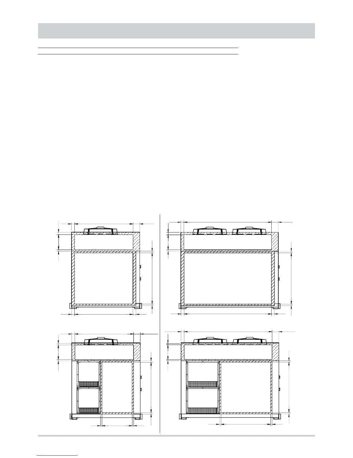
The following is a list of the position and sizes of the flanges necessary for proper design and subsequent connection of the air
ducts.
Standard air flow and inlet connection
Models 35.1 - 45.1 - 55.1 Models 70.2 - 90.2 - 110.2
MF
R
63 1197 63
03 3501
43
23
64
62 1200
013
MF
R
63 1797 63
03 3501 43
62 1800 138
138
23 013 64