37
CONNECTIONS
Hydraulic connections
Internal coil condensate discharge connection (compulsory)
It is very important that this operation be performed with particular care by specialized personnel. For the sequence follow these
instructions:
• . Connect the condensate discharge tube.
• . Use a siphon to eliminate the negative pressure created by the fan, thereby preventing the intake of gas by the discharge tube
and ensuring the regular discharge of the condensate.
• . Connect the opening to a drain pipe discharge network. Do not use white water or sewage drains so as to prevent the intake
of odors in case of water evaporation.
• . After the first hours of operation in the cooling mode, check that the siphon is effective.
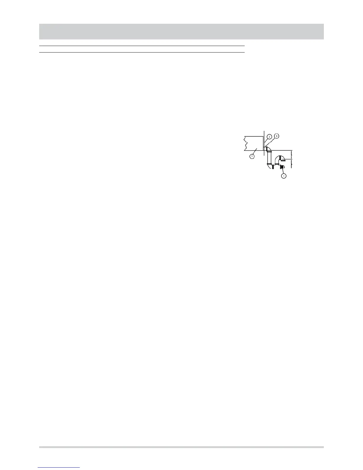
1. Condensate collection drain pan inside the unit is constructed of stainless steel and has
been opportunely inclined to facilitate drainage.
2. External surface of the longitudinal member for the base.
3. Opening attached to the longitudinal member.
4. Example of a siphon made with PVC components, including a cap for cleaning (under
the responsibility of the user).
IMPORTANT:
• . Place the discharge tube so as not to cause mechanical stress on the unit’s discharge connector.
• . When the accessories for the water coil for post-heating only and the droplet separator are present, repeat the instructions
listed above also for the second discharge outlet.
• . See the drawings below for the position and dimensions of the connectors.
External coil condensate discharge connection (optional)
The drainage of the external coil is guaranteed by a drain pan equipped with a connector.
This discharge outlet (one for each external coil) was included to make it possible to convey the external coil’s runoff and
condensate. This connection is optional and at the discretion of the engineer and/or installer. It is possible to use also white water
or sewage drains, because no danger exists of contamination with the treated air. Use a siphon to compensate for the negative
pressure created by the fan, thereby preventing the intake of outside air by the discharge tube and ensuring the regular discharge
of the condensate (ƒPmax = 150 Pa). If no siphon is installed, the regular discharge of the condensate will be conditional upon the
amount of water collected in the drain pan.
IMPORTANT:
• . Place the discharge tube so as not to cause mechanical stress on the unit’s discharge connector.
• . See the drawings below for the position and dimensions of the connectors.
• . Do not cap unless there is a connection to some type of discharge tube.
Connection of water coil for post-heating only (optional)
The water coil for post-heating only is installed at the factory and positioned vertically in the internal fan’s intake section. The
connection between the coil and the water inlet and outlet openings, located on the machine, is ensured by a tubes unit or a 3-way
valve unit, which is also installed at the factory.
The position of the connectors for both solutions is the same. For their placement and dimensions, refer to the drawings below.
Connect the coil using the tube diameters listed in the table.
Remove the caps on the openings only immediately before making the hydraulic connections.
The connection tubes must not cause vibrations to the coils due to its own weight or due to thermal expansion. Install any
necessary supports and expansion compensators. Attach suitable connectors to allow easy disconnection and removal of the
coils. When making the connections, do not twist the connectors and be sure to observe the proper direction of the inlet and outlet
flows.
The water coil circuit can be used with water or with glycol solutions if required by the installation. If the water used causes erosion
or deposits, it is advisable to engage the services of a specialist in water treatment. Insulate all the water tubes that could be
exposed to freezing temperatures so as to prevent the freezing of the coil and heat loss. The water distribution network must be
equipped with vents at the points in which it is probable that air could become trapped
L
≥
50mm