51
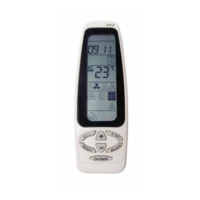
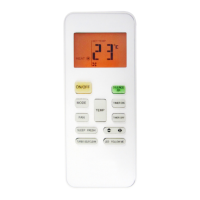
CONTROL SYSTEM
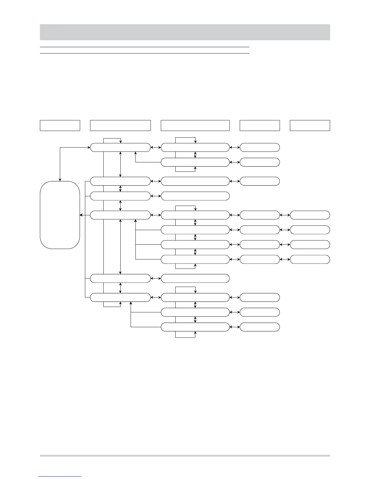
Main structure
The menu of the control system has a tree structure based on four different levels. By scrolling the menu with the “mode” and “set”
buttons it is possible to display and modify :
• set point
• analogue inputs (probes for temperature, humidity, CO2 …)
• active alarms
• operating parameters
• hours of operation
Set point :
S E t
Set point Cooling :
C o o
Set point Heating :
HE A
Set point value
Set point value
Level 1 Level 2 Level 3 Level 4Level 0
Analogue inputs :
t P Input AI1 … AI8 :
t 0 1
...
t 0 8
Input value
Alarms :
E r r
Active alarms codes
Parameters :
P a r
Configuration :
C n F
Parameter
H. .
Parameter value
Adjustment :
r e
Parameter
b . .
Parameter value
Antifreeze :
F r o
Parameter
r . .
Parameter value
Free cooling :
F r C
Parameter
L . .
Parameter value
Password :
P ss
Password value
Hours of operation :
O Hr
Hours compressor 1 :
O H1
Number of hours
Hours internal fan :
O Hp
Number of hours
Hours compressor 2 :
O H3
Number of hours
Probe value ST1
8 8
.
8
o
Active alarm code
E . .
To go from one level to that below, press the “mode” and “set” buttons at the same time. To go to the level above, keep the two
buttons pressed for at least 2 seconds.
To scroll the menu up and down, inside the same level, use the “mode” and “set” buttons respectively.