4. Commissioning
4−15
Festo P.BE−CPV−EN en 0503g
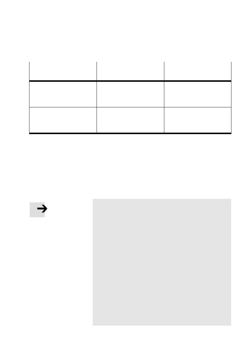
Desired pneumatic
operating status
Prerequisites Remarks
EMERGENCY STOP of pressure
zones
Guarantees the controller
function for the auxiliary pilot
air despite the complete supply
being switched off
The controller regulates the
auxiliary pilot air of all valves
sub−bases on a valve
terminal
Slow start−up after EMERGENCY
STOP
If there are control signals, the
auxiliary pilot air must have a
pressure of 3...8 bar immedia
tely after being switched on.
Tab.4/7: Pneumatic operating states
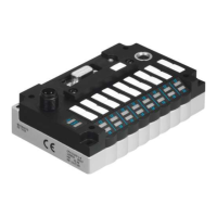
LED display of the valves
There is a yellow LED for every valve solenoid coil (see dia
gram). With a ready to operate CPV valve terminal, this LED
indicates the switching status of the valve solenoid coils.
Please note
The LEDs show the signal states only when there are valve
coils at the relevant valve locations. For this purpose the
load voltage must lie within the permitted tolerance.
Note the assignment of the LEDs to the relevant manual
override (see also following diagram).
Note the following with the IC connection:
LED
in the front plug connector to upper manual
override (14)
LED in the rear plug connector to lower manual
override (12)
Note the following with the MP, ASI, DI and CP connec
tions:
Lower LED in the connector cover to upper manual
override (14)
Upper LED in the connector cover to lower manual
override (12)
 Loading...