LED (green) Meaning Measure
lights
up
Logic 1 (signal is present). –
off
Logic 0 (signal not present). –
Tab. 110: LED display input status, digital
3.8.2
Diagnostic interface
The diagnostic interface for the CPX terminal makes it possible to locate a malfunction to a specific
component of the CPX terminal or of the Motion Terminal. For details, see the manual of the CPX
terminal
è
1.1 Applicable documents.
The source of the malfunction within the Motion Terminal can be identified using the channel informa-
tion.
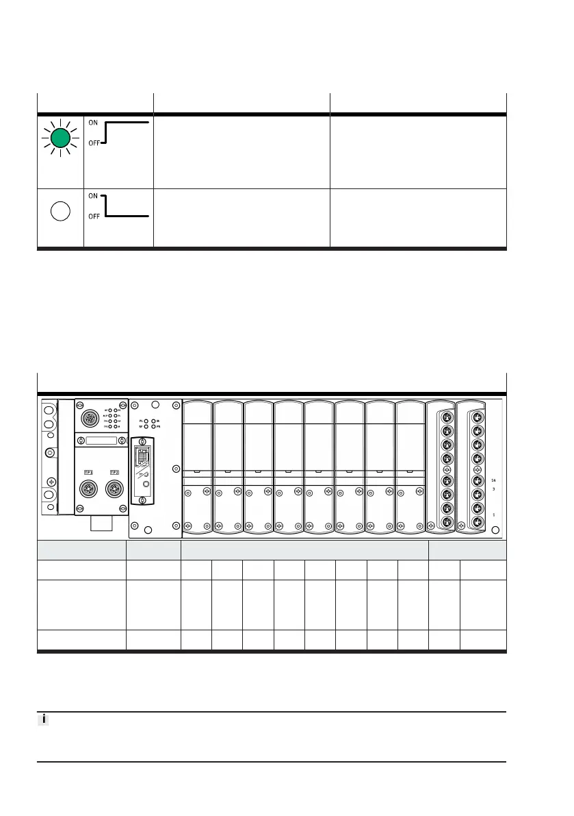
Allocation of the channel numbers (without additional CPX modules)
Controller Valve slot Input module
0 1 2 3 4 5 6 7 1 2
Input channel E0 – – – – – – – – E1,
E2 …
E9
E10,
E11 …
E18
Output channel A0 A1 A2 A3 A4 A5 A6 A7 A8 – –
Tab. 111: Allocation of the channel numbers (without additional CPX modules)
Channels E2 … E9 und E11 … E18 correspond to the individual inputs (0 … 7) of the applicable input
module.
Depending on the structure of the CPX terminal, the channel numbers shown above must be added to
the number of the I/O channels that can be assigned to additional modules in the CPX terminal.