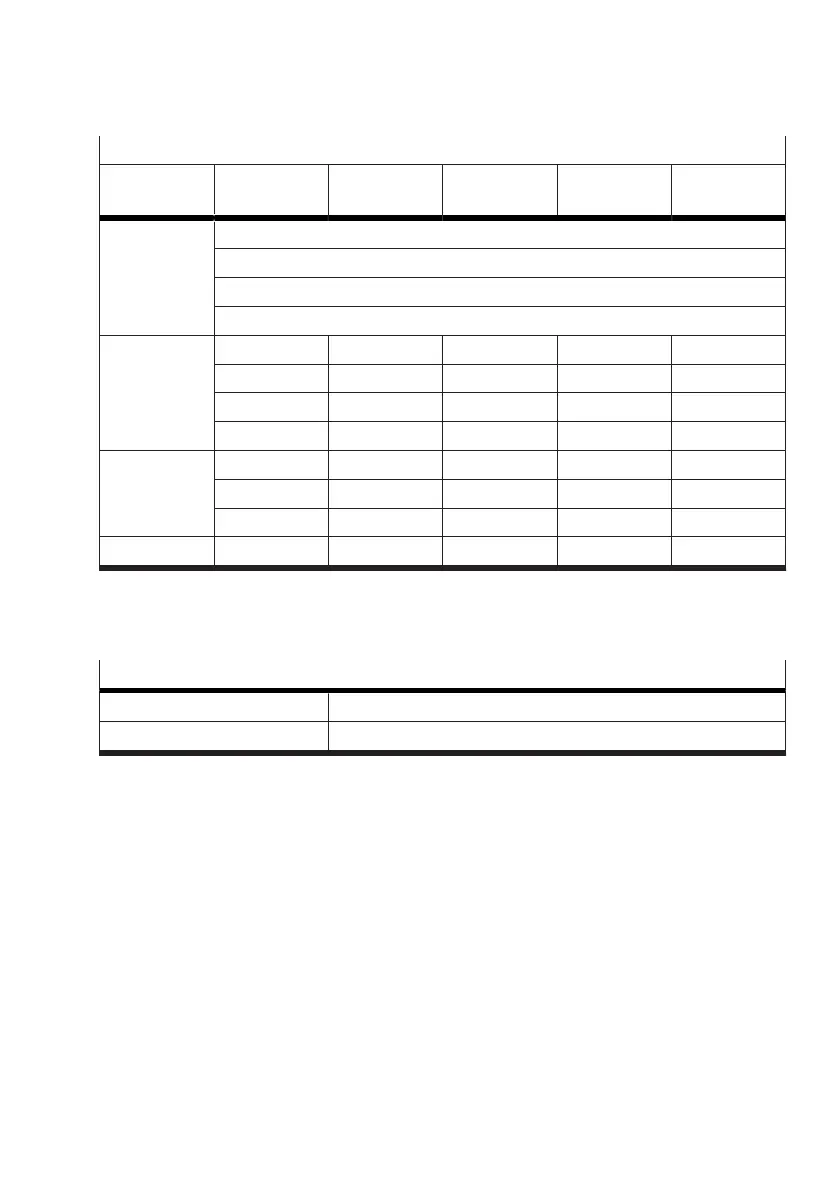
Valve at slot 1
Parameter
set 3
Motion App A Motion App B Motion App C Motion App D Motion App …
System param-
eters
Sys. par. a
Sys. par. b
Sys. par. c
Sys. par. …
Application
parameters
App. par. m App. par. m App. par. m App. par. m App. par. m
App. par. n App. par. n App. par. n App. par. n App. par. n
App. par. o App. par. o App. par. o App. par. o App. par. o
App. par. … App. par. … App. par. … App. par. … App. par. …
Tuning param-
eters
Tun. par. x Tun. par. x Tun. par. x Tun. par. x Tun. par. x
Tun. par. y Tun. par. y Tun. par. y Tun. par. y Tun. par. y
Tun. par. … Tun. par. … Tun. par. … Tun. par. … Tun. par. …
Teach-in data Data record 1 Data record 2 Data record 3 Data record 4 Data record 5
Tab. 38: Example of the structure of parameter set 3
3.4.4
Setpoint and actual values
Setpoint and actual values can be written and read cyclically by the process data.
Setpoint and actual values
Writing setpoint values Output data (PDO, Process Data Output)
Reading actual values Input data (PDI, Process Data Input)
Tab. 39: Setpoint and actual values
The setpoint and actual values are specific to the individual Motion Apps. The structure of the process
data is described in section (
è
3.5 Communication between PLC and Motion Terminal).
3.4.5 Waiting time between Motion Apps
In the following cases, calibration of the associated valve takes place before the Motion App that has
been started is executed:
– Following a restart of the Motion Terminal, a Motion App is started for the first time.
Exception: Motion App #01 in operating mode "controlled"
– After execution of Motion App #01 in operating mode "controlled", Motion App #01 is started for
the first time in the operating mode "regulated" or another Motion App is started.
This calibration can take up to 60 seconds and will be performed automatically prior to execution
of the Motion App. The calibration can be viewed as a return value in the process data
è
Tab. 51
Information on invalid output data.