The inputs are evaluated only by the controller of the Motion Terminal. The states of the inputs cannot
be queried directly by the higher-order controller. However, various Motion Apps provide information
about the states or values of the sensors.
The characteristics of the peripherals that are connected to the inputs of the input module must be
made known to the system (input module configuration).
Required specifications
è
3.4.3.4 Sensor parameters:
–
Sensor type
– Sensor orientation (for position sensors on the analogue input module CTMM-S1-A-...)
3.1.1.6 Cover plate VABB-P11-27-T
Vacant valve or module positions must be sealed with a cover plate.
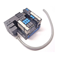
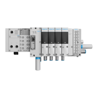
3.1.1.7 Valves
The valves together with the controller form the central component of the Motion Terminal. A valve
VEVM-S1- 27-… in each case contains 4x 2/2-way dynamic control valves with piezo pilot valves
interconnected to form a full bridge. Each valve is additionally equipped with sensors so as to be able
to detect the actual status of the valve and regulate it.
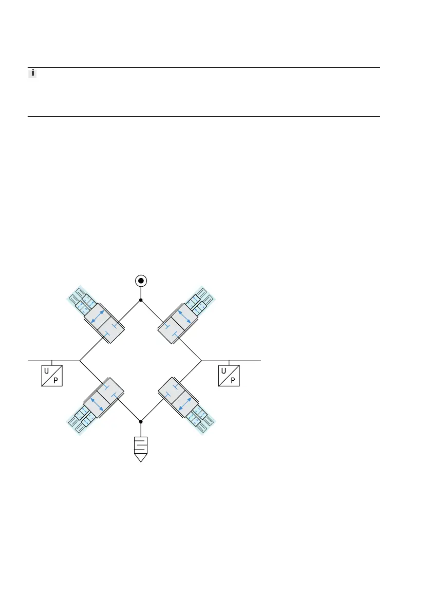
Fig. 8: Switching the full bridge of a valve slice
One of the licensed Motion Apps can be run on each valve, independently of the other valves.
Numbering of the valves
The slots for the valves are numbered sequentially in ascending order from left to right, starting at the
right of the controller with slot 0. The number (address) of a valve is given by the slot on which it is
mounted.
3.1.2 Display components
For behaviour of display components and diagnostics options see
è
3.8.1 LED display components.