Seite/Page 4 Inhalt/Contens 14.7.16
Inhalt / Contens
(over 6 months): 31
5.8 ........................................................................................................................................................ .... 32
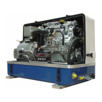
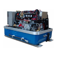
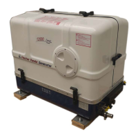
6 Panda 5000i PMS generator .................................................................................................................. ..... 33
6.1 Type plate at the generator............................................................................................................. .... 33
6.1.1 Right Side View .............................................................................................................. .... 34
6.1.2 Left Side View ................................................................................................................. .... 35
6.1.3 Front View ....................................................................................................................... .... 36
6.1.4 Back View ....................................................................................................................... .... 37
6.1.5 View from Above ............................................................................................................. .... 38
6.2 Details of function units................................................................................................................... .... 39
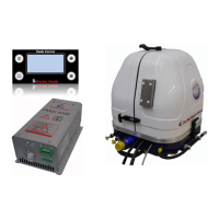
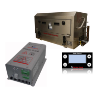
6.2.1 Remote control panel - see iControl manual .................................................................. .... 39
6.2.2 Components of the Cooling System (Raw Water) .......................................................... .... 39
6.2.3 Components of the Cooling System (Fresh Water) ........................................................ .... 40
6.2.4 Components of the Fuel System .................................................................................... .... 41
6.2.5 Components of Combustion Air ...................................................................................... .... 42
6.2.6 Components of the Electrical System ............................................................................. .... 43
6.2.7 Components of the Oil Circuit ......................................................................................... .... 44
6.2.8 Sensors and switches for operating surveillance ............................................................ .... 44
6.3 Operation Instructions - see separate control panel manual........................................................... .... 46
6.3.1 Daily routine checks before starting - See iControl manual. ........................................... .... 46
6.3.2 Starting Generator - See iControl manual. ..................................................................... .... 46
6.3.3 Stopping the Generator - See iControl manual. .............................................................. .... 46
7 Installation Instructions.......................................................................................................................... ..... 47
7.1 Personal requirements.................................................................................................................... .... 47
7.1.1 Hazard notes for the installation ..................................................................................... .... 47
7.2 Place of installation ......................................................................................................................... .... 49
7.2.1 Preliminary remark .......................................................................................................... .... 49
7.2.2 Preparing the base - placement ...................................................................................... .... 49
7.2.3 Advice for optimal sound insulation ................................................................................ .... 50
7.3 Generator Connections................................................................................................................... .... 50
7.4 Installation of the cooling system - raw water ................................................................................. .... 51
7.4.1 General information ........................................................................................................ .... 51
7.4.2 Installation of the through hull fitting in Yachts - scheme ................................................ .... 51
7.4.3 Quality of the raw water sucking in line .......................................................................... .... 51
7.4.4 Generator installation above waterline ........................................................................... .... 52
7.4.5 Generator installation below waterline ............................................................................ .... 52
7.4.5.1 Raw water installation scheme......................................................................... .... 53
7.5 Installation of the cooling system - fresh water ............................................................................... .... 54
7.5.1 Position of the external cooling water expansion tank .................................................... .... 54
7.5.2 De-aerating at the first filling of the internal cooling water circuit .................................... .... 54
7.5.3 Pressure Test for Controlling the Cooling Water Circuit ................................................. .... 55
7.6.1 Installation of the standard exhaust system .................................................................... .... 56
7.7 .Installation of the waterlock............................................................................................................ .... 56
7.7.1 Possible cause for water in the exhaust hose ................................................................ .... 57
7.7.1.1 Possible cause: exhaust hose.......................................................................... .... 57
7.7.1.2 Possible cause: cooling water hose ................................................................. .... 57