Instruction Manual
D103412X012
Detailed Setup—AO Function Block
July 2013
121
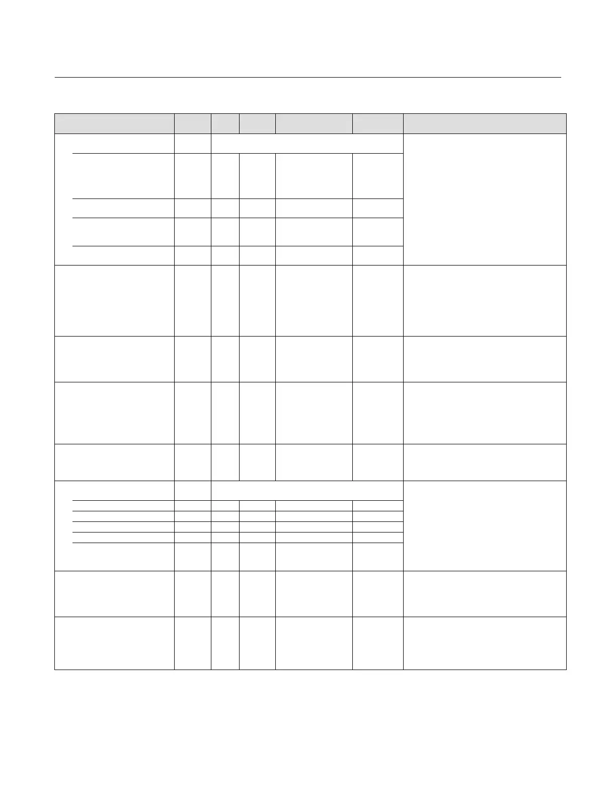
Table 4‐25. Analog Output Function Block Parameter Definitions (Continued)
Description
Initial
Value
Range
Block
Mode
RO /
RW
Index
Number
Label
PARAMETER_NAME
Block Mode
MODE_BLK
5
Data Type: DS‐69
Valid Bits: 7: OOS, 6: IMAN, 5: LO, 4: MAN, 3: AUTO,
2: CAS, 1: RCAS
The actual, target, permitted, and normal modes of
the block.
Target: The requested block mode
Actual: The current mode of the block
(Note: Bit 6 (IMAN) is valid for ACTUAL only)
Permitted: Allowed modes for Target
Normal: Most common mode for Target
TARGET
5.1 RW ALL
OOS
MAN
AUTO
AUTO‐CAS
AUTO‐RCAS
OOS until
block is
configured,
then last valid
target
ACTUAL
5.2 RO ALL OOS
PERMITTED
5.3 RW ALL
OOS+MAN+AUTO+
CAS+RCAS
OOS+MAN+A
UTO+
CAS+RCAS
NORMAL
5.4 RW ALL AUTO
Block Error
BLOCK_ERR
6 RO N/A
1: Block Configuration
Error
3: Simulate Active
4: Local Override
5: Device Fault State Set
8: Output Failure
14: Power‐up
15: Out‐of‐Service
Dynamic
Data Type: Bit String (2 byte)
0=inactive
1=active
This parameter reflects the error status associated
with the hardware or software components
associated with a block. It is a bit string, so that
multiple errors may be shown. See table 4‐24.
Process Variable
PV
7 RO N/A
PV Status set equal to
READBACK status
Dynamic
Data Type: DS‐65
The process variable used in block execution. This
value is converted from READBACK to show the
actuator position in the same units as the setpoint
value.
Set Point
SP
8
OOS
MAN
AUTO
PV_SCALE +/- 10% Dynamic
Data Type: DS‐65
The SP of the analog block. Can be derived from
CAS_IN, RCAS_IN in normal modes, or can track PV
in MAN, IMan or LO modes. IO_OPTS is used to
determine value of SP in MAN, IMan or LO. If no
IO_OPTS for SP tracking are set, SP will freeze when
mode changes from CAS or RCAS.
Output
OUT
9
MAN
OOS
OUT_SCALE +/- 10% Dynamic
Data Type: DS‐65
The primary value and status calculated by the
block in Auto mode. OUT may be set manually in
Man mode.
Simulate
SIMULATE
10
Data Type: DS‐82
Allows the analog input to be manually supplied
when simulate is enabled. When simulation is
disabled, the simulate value and status track actual
value & status.
SIMULATE_STATUS 10.1 RW ALL 0
SIMULATE_VALUE 10.2 RW ALL 0
TRANSDUCER_STATUS 10.3 RO ALL 0
TRANSDUCER_VALUE 10.4 RO ALL 0
ENABLE/DISABLE 10.5 RW ALL
0: Not Initialized
1: Simulation Disable
2: Simulation Active
1: Simulation
Disabled
Process Value Scale
PV_SCALE
11 RW OOS
EU at 100%
EU at 0%
Units index
Decimal Point
100
0
%
2
Data Type: DS‐68
The high and low scale values, engineering units
code, and number of decimal places to be used in
displaying the PV parameter and parameters which
have the same scaling as PV.
Transducer Scale
XD_SCALE
12 RO OOS
EU at 100%
EU at 0%
Units index
Decimal
Point
100 only
0 only
% only
2
Data Type: DS‐68
The high and low scale values and engineering
units code are read only. This parameter
determines the number of digits to the right of the
decimal point used with the value obtained from
the transducer for a specified channel.
-Continued-

 Loading...


