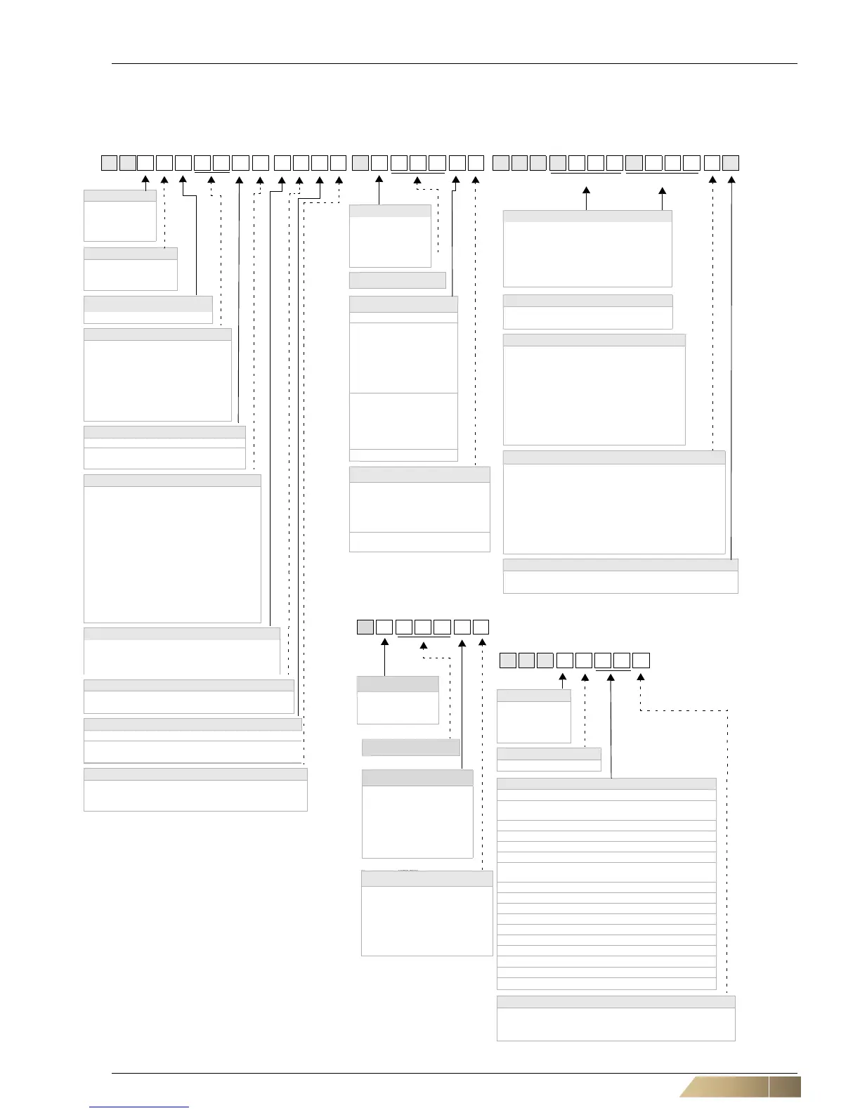
Unit type code MATRIX Controller Valve code
G H1 1.UWW3.F E0C2 D3.001.BA V G H.R325R216.1L
Model size
1 = Model size 1
2 = Model size 2
3 = Model size 3
4 = Model size 4
Capacity stage
1 = Capacity stage 1
2 = Capacity stage 2
3 = Capacity stage 3
Air-flow function
U = Recirculating-air unit
Medium function
Heating only
0W = PWW
Cooling only
W0 = PCW (pumped chilled water)
Cooling or heating
WC = Pumped chilled - warm water
Cooling and heating
WW =
Pumped chilled - warm water
Medium connection
Ceiling
3=left
4=right
Speeds
Terminal box with terminal strip
A = Speed stages 1, 2, 3
B = Speed stages 2, 3, 4
C = Speed stages 3, 4, 5
E = Speed stages 1, 3, 5
F = Min..Max (EC motor)
Metal-sheet electric switch cabinet with termi-
nal block or for integrated control system
K = Speed stages 1, 2, 3
L Speed stages 2, 3, 4
M Speed stages 3, 4, 5
O Speed stages 1, 3, 5
S = Min..Max (EC motor)
Thermal contact
0=
AC motor - 5 speeds - with integrated motor protection
E = EC motor - continuous control - with integrated
motor protection
Condensate pump
0 = with condensate drain
1 = with condensate pump
Fan chamber
A = without fan chamber**
B = with fan chamber
C
= with fan chamber - self-contained
Filters
0 = without mat filter
2 = G2 mat filter
4 = G4 mat filter
Controller type
0=Terminal box/
Matrix 500
2 = MATRIX 2000
3 = MATRIX 3000
4 = MATRIX 4000
Controller package no.
Control panel
IP20
A = MATRIX OP21C
B = MATRIX OP30C
C = MATRIX OP31C
D = MATRIX OP44C
E = MATRIX OP50C
F = MATRIX OP51C
U = MATRIX OP20C
1=CMS
2=CMT 40
3=CMT 20
4=CMT 2Z
J = CET.ACEC
Z = without control panel
Unit type
Master unit, control panel
A=
Individual/master unit,
control panel included
C=
Master unit
without control panel
D=
Slave unit
without control panel
Function type
R=3-point 230V
T=2-point 230V
N=3-point 24V
Q=2-point 24V
S = 0-10 V, 24 V
C=
3-point 230 V + 2 contacts
Valve body
2=2-way
3=3-way
K
vs
-value
03 = K
vs
0,25 (R, N, S, C)
04 = K
vs
0.40 (R, N, S, C)
06 = K
vs
0.63 (R, N, S, C)
10 = K
vs
1,0 (R, N, S, C)
16 = K
vs
0,40 (R, N, S, C, T, Q)
25 = K
vs
2.5 (R, N, S, C, T, Q)
40 = K
vs
4.0
(R, N, S, C, T, Q)
63 = K
vs
6.3
(R, N, S, C, T, Q)
80 = K
vs
8.0 (R, N, S, C, T, Q)
Connection/shut-off
0 = Inlet/outlet flow with outside thread
1 = Inlet/outlet with solder fitting
2 = Inlet/outlet + ball trap with external screw thread
3 = Inlet/outlet + ball trap with solder fitting
4 = Inlet + ball trap/
outlet + shut-off valve with external screw thread
5 = Inlet + ball trap/
outlet + shut-off valve with solder fitting
Medium connection
L = Left
R=Right
Cooling/heating circuit Heating circuit
Model size
1 = Model size 1
2 = Model size 2
3 = Model size 3
4 = Model size 4
Accessory class
A = Air-side accessories
Accessory types
Inlet side (intake)
03 =
Air-intake plenum with round connector (not self-con-
tained)
11 = Intake flexible connection
21 = Intake sound absorber connection
51 = Air intake grille (intervention protection)
Discharge side (outlet)
04 =
Discharge plenum with round connector (self-con-
tained)
11 = Air discharge flexible connection
21 = Air discharge sound attenuator connection
91 = Air discharge transition piece
Other
61 = Suspension rail - 950 mm
62 = Suspension rail - 1550 mm
63 = Suspension rail - 2150 mm
71 = Seal cap for round connector (self-contained)
82 = Spare filter G2
84 =
Spare filter G4
Intake - discharge side
1 = Inlet side (intake)
2 = Discharge side (outlet)
3 = Other
Z G H.1 A 0 3 1
Accessories code
*) Connection side from front, viewing the discharge
**) not certified as of VDI 6022
***) Required accessories for mounting on discharge side from
FläktGroup
Controller type
0 = Terminal box
1=
Module 3010
2=
Module 3020
A 0.0 0 1.1 A
ISYteq Controls
Controller package Nr.
Control panel
1 = CET.ACEC
2=CMT 4D
3=CMT 2D
4=CMT 2Z
A = ISYteq LCD
B = ISYteq Touch
Z = without control panel
UU = MATRIX OP20C
Unit type
Master unit, control panel
A=
Individual/master unit,
control panel included
C=
Master unit
without control panel
D=
Slave unit
without control panel