Technical Description HyPower-Geko
18 FläktGroup DC-2014-0022-GB 2018-05/R5 • Subject to modifications
2.5 Unit data
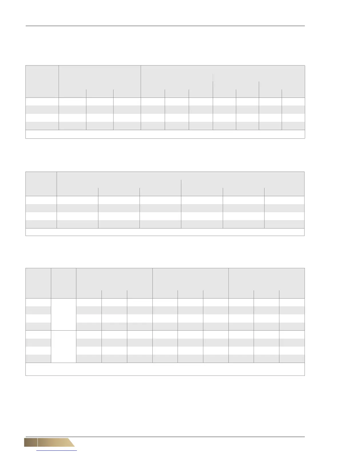
2.5.1 Unit weight and water charge of heat exchanger
2.5.2 Air flow rate
2.5.3 Acustic values
Model size Weight1) [kg] Water charge[l]
2-pipe 4-pipe
Cooling circuit Heating circuit
VK A VK B VK C CS 1 CS 2 CS 3 CS 1 CS 2 CS 1 CS 2
1 27 33 36 1,2 2,2 3,3 1,7 2,2 0,7 1,2
2 37 45 48 1,7 3,3 4,8 2,5 3,3 0,9 1,7
3 48 59 62 2,2 4,3 6,4 3,2 4,3 1,2 2,2
4 60 75 79 2,9 5,8 8,5 4,3 5,8 1,6 2,9
1) Max. basic unit weight without accessories ... capacity stage VK .... Fan chamber
Tab. 2-13: Unit weight and water charge of heat exchanger
Model size
Air volume flow [m³/h] *
)
AC motor (Min. / Max.) EC motor (Min. / Max.)
VK A VK B VK C VK A VK B VK C
1 700 / 1445 685 /1165 670 / 1090 505 / 1170 415 / 1095 415 / 1080
2 875 / 2640 845 / 2070 825 / 1725 740 / 2300 525 / 2110 500 / 1965
3 780 / 3200 720 / 2670 700 / 2565 1115 / 3460 815 / 3045 735 / 2745
4 2595 / 4490 2460 / 3740 2400 / 3440 1455 / 4540 970 / 4050 880 / 3695
*) at 0 Pa external pressure VK .... Fan chamber
Tab. 2-14: air volume flow
Model
size
Fan type
Sound power level
– intake-side [dB(A)]*)
Sound power level - discharge
side [dB(A)]*)
Sound power level - casing
radiation [dB(A)]*)
Min. / Max. Min. / Max. Min. / Max.
VK A VK B VK C VK A VK B VK C VK A VK B VK C
1
AC
52 / 68 56 / 67 55 / 64 50 / 67 55 / 67 56 / 66 - 48 / 59 49 / 57
2 49 / 70 50 / 68 49 / 65 48 / 68 50 / 68 50 / 67 - 47 / 60 47 / 58
3 46 / 72 44 / 69 41 / 67 44 / 72 44 / 70 44 / 70 - 41 / 61 42 / 61
4 63 / 74 65 / 71 63 / 69 61/74 63 / 74 64 / 72 - 59 / 63 56 / 61
1
EC
52 / 74 46 / 72 42 / 68 51 / 73 48 / 73 45 / 72 - 43 / 65 37 / 60
2 45 / 75 39 / 71 37 / 67 42 / 75 41 / 73 40 / 72 - 35 / 64 30 / 58
3 54 / 77 48 / 75 46 / 71 50 / 76 49 / 75 48 / 75 - 41 / 68 37 / 62
4 50 / 78 46 / 75 43 / 72 46 / 76 43 / 74 42 / 73 - 40 / 68 36 / 62
*) For control voltage 2-10V at 0 Pa external pressure (free intake and discharge)
VK .... Fan chamber
Tab. 2-15: Acoustic values of the basic unit