Hydraulic Connection HyPower-Geko
52 FläktGroup DC-2014-0022-GB 2018-05/R5 • Subject to modifications
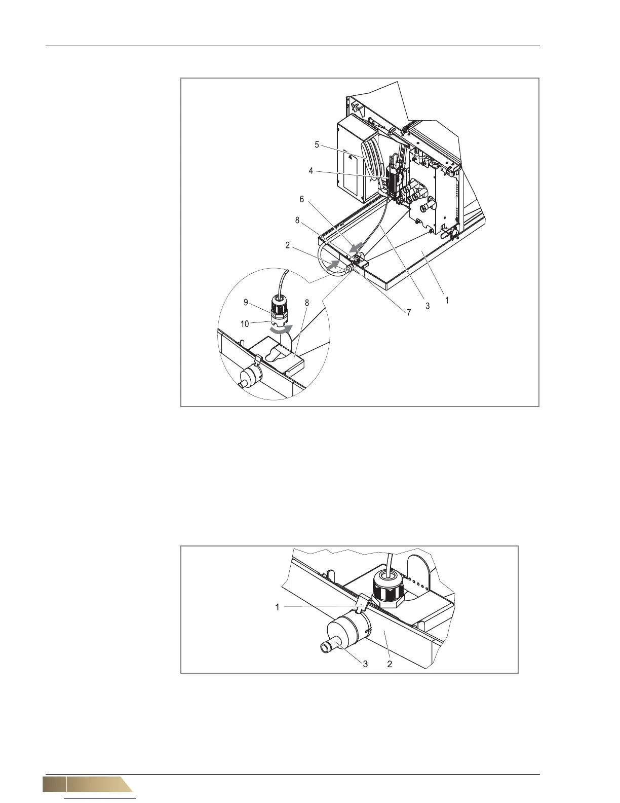
5.6 Connecting condensate pump
Pos. 1: Condensate tray
Pos. 2: Plastic-end piece of the
suction hose of the
condensate pump
Pos. 3: Inlet hose
Pos. 4: Condensate pump
Pos. 5: Pressure hose (1.5 m
long)
Pos. 6: Fill level sensor
Pos. 7: Drain connection of
the condensate tray
with O-ring
Pos. 8: Sensor holder
Pos. 9: Cable opening
Pos. 10: Nut of the cable gland
• Execution including fill level sensor (see fig. 5-20, Pos. 6) attach to the bracket
(see fig. 5-20, Pos. 8) and secure the cable penetrations
with a nut (see fig. 5-20, Pos. 10).
• Lubricate the drain connection of the condensate tray including its O-ring (see fig. 5-
20, Pos. 7) with lubricant. Set the plastic end piece of the suction hose of the
condensate pump (seefig. 5-21, Pos. 3) on the outlet fitting of the condensate tray
(seefig. 5-21, Pos. 2) until it sits firmly. For for the assembly of the end piece, be
sure that the half-round hole at the edge of the end piece (see fig. 5-21, Pos. 1) is
on the upper side.
Pos. 1: Half-round hole at the
edge of the end piece
Pos. 2: Condensate tray
Pos. 3: Plastic end piece
of the suction hose
of the condensate
pump
The end of the pressure hose of the condensate pump must be connected with free
discharge to the on-site condensate discharge facility. If the pipe extension is run with
additional counter-pressure, e.g. by extending the factory-provided pressure hose, the
actual discharge volume is reduced by the additional resistance (refer to
Tab. 5-4 and
fig. 5-22).
Fig. 5-20: Connecting condensate pump
Fig. 5-21: Assembly of the end piece of the pump suction hose assembly