Commissioning HyPower-Geko
100 FläktGroup DC-2014-0022-GB 2018-05/R5 • Subject to modifications
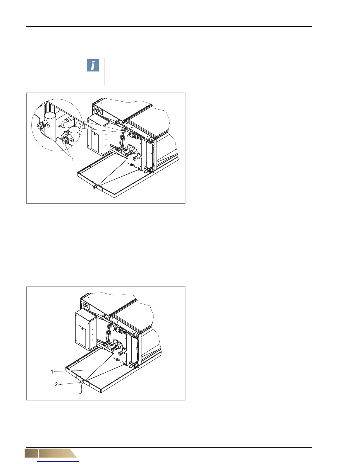
7.3 Vent the unit
To ensure that the exchanger is charged with heating/cooling medium, it must be air
vented.
7.4 Checking the condensate drain
This checkpoint only applies to cooling units without condensate pump!
Condensate forms as a result of unit operation in cooling mode, the same applies to
non-insulated pipes. Check
• that the connection of the condensate tray (fig. 7-7, Pos. 1) is performed so that
condensate can drain freely. At the same time a sufficient slope of the condensate
line must be considered.
User instructions!
Protect electrical hardware and furniture from escaping splash water.
• Open all shut-off and control valves.
• Open the venting screw(s) with a suitable tool
(see fig. 7-6).
• Close the air vent screw again only if heating/
cooling medium is still pouring out.
• Proceed in the same way with all remaining air
vent screws. Depending on the unit model,
there are additional 1 or 2 air vent screws.
Pos. 1: Air vent screws
Fig. 7-6: Air venting heat exchanger
Pos. 1: Coil drip tray
Pos. 2: Condensate drain
Fig. 7-7: Drainage of the condenser water

 Loading...
