HyPower-Geko Mounting
FläktGroup DC-2014-0022-GB 2018-05/R5 • Subject to modifications 29
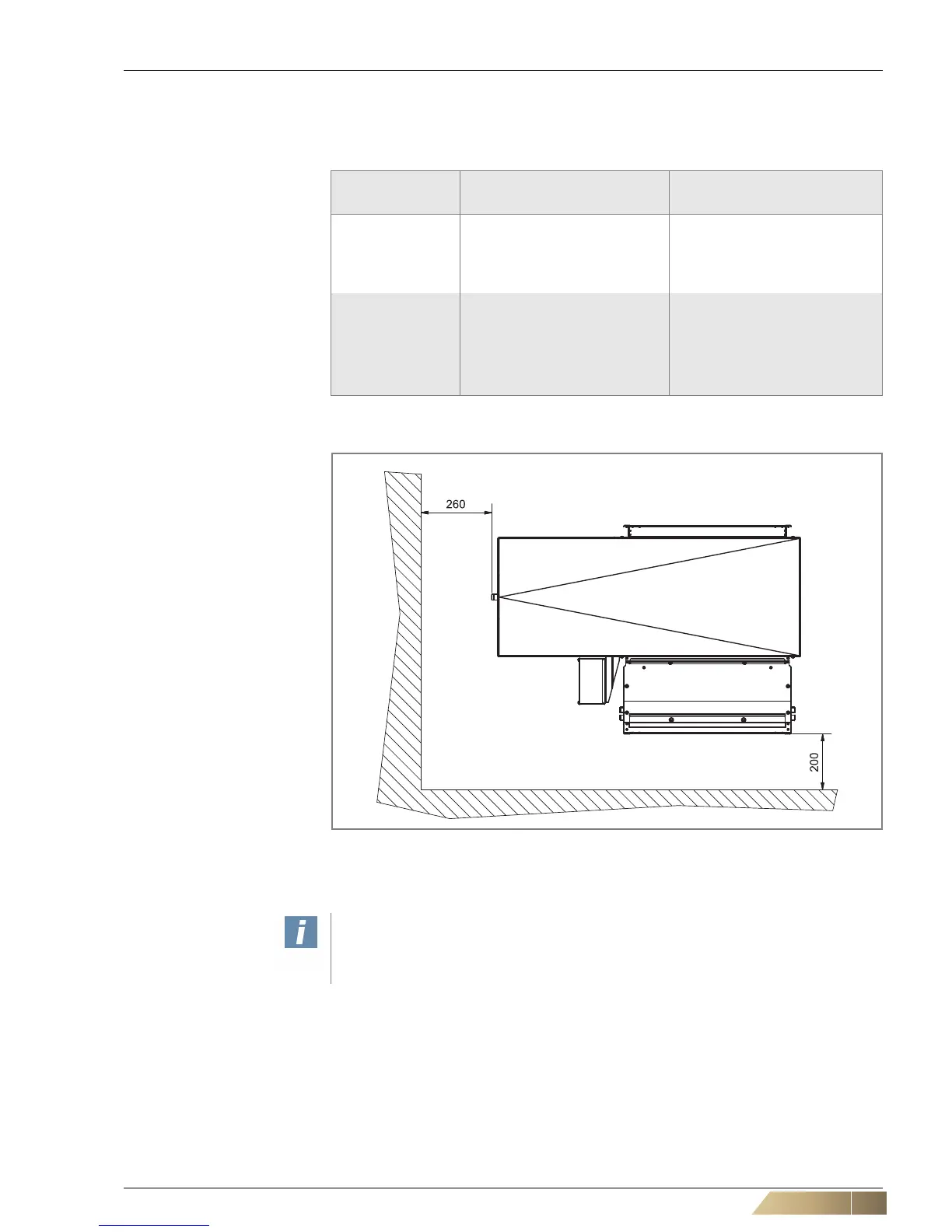
4.3 Pre-installation work
Depending on the connection side, the pipes can be connected from the left or from
the right. The following installation clearances must be observed:
Position No.,
refer to fig. 4-3
REASON Installation
clearance [mm]
1
for proper inflow of the air from
the back (does not apply if
connected to an on-site intake
duct)
to the back
200
2
for installation work, e.g. for
lateral connection to the on-
site valve piping
to the side
260
without valve accessories
560
with valve accessories
Tab. 4-3: Installation clearances
Fig. 4-3: Assembly spacing (viewing from below)
*) Dimensions in brackets apply to valve accessories for assembly of factory valve
equipment
 Loading...

