HyPower-Geko Technical Description
FläktGroup DC-2014-0022-GB 2018-05/R5 • Subject to modifications 19
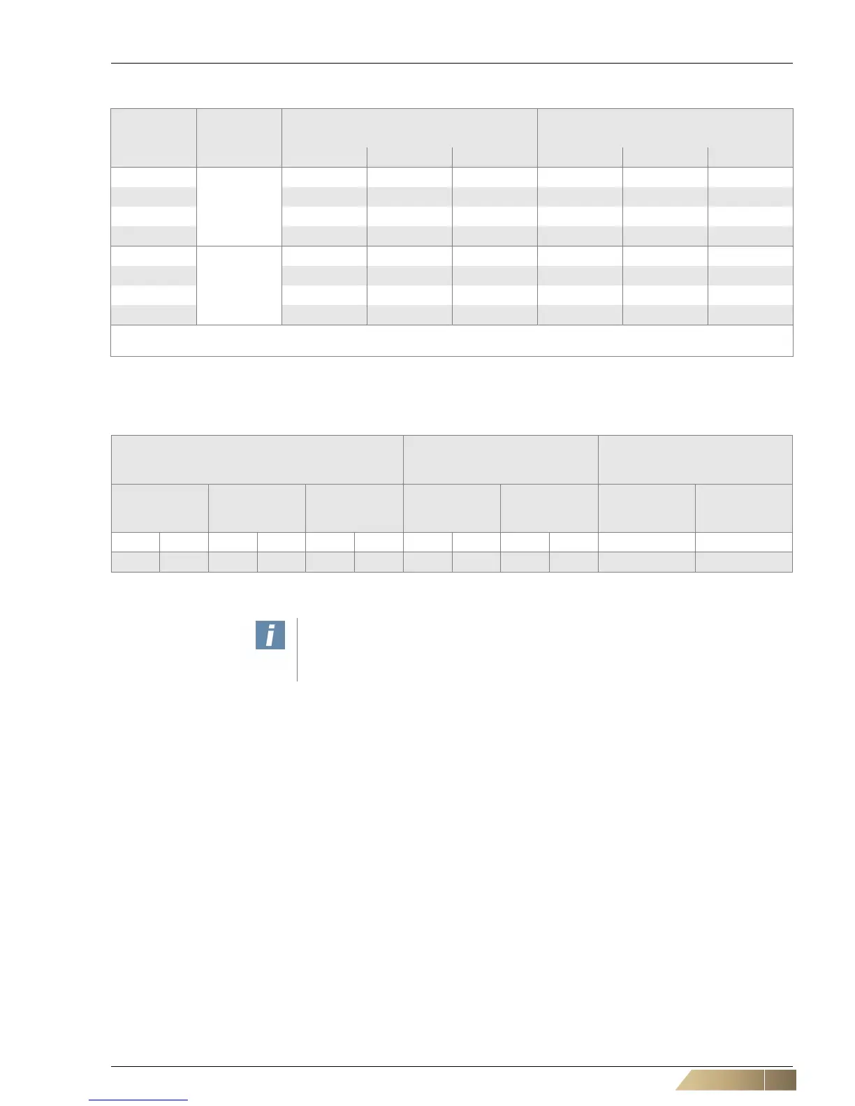
2.5.4 Electrical data for fans
2.5.5 Electrical data of valve actuators
2.6 Condensate pump
In cooling units, condensate may form and is collected in the coil drip tray. If a slope
for condensate drainage is not fitted, a condensate pump must be installed. This pump
drains condensate into drainage pipework located higher upstream.
2.6.1 Function of condensate drain
A separate level sensor is installed on the side of the unit at the condensate tray other than
the condensate pump, which performs the following functions:
– Start of the condensate pump when the condensate level exceeds 4 mm from the
bottom of the condensate tray.
– Switch-off of the condensate pump after the condensate is pumped out.
– Sends the signal ALARM if the maximum permitted height of the condensate level
of 12 mm from the bottom of the condensate tray is exceeded.
Model size Fan type
Current consumption [A]*
)
Power consumption [W]*
)
Min. / Max. Min. / Max.
VK A VK B VK C VK A VK B VK C
1
AC
0.64 / 0.98 0.57 / 0.75 0.56 / 0.69 131 / 224 118 / 172 116 / 157
2 0.93 / 1.90 0.87 / 1.30 0.85 / 1.15 180 / 431 174 / 293 171 / 254
3 0.94 / 2.15 0.89 / 1.76 0.92 / 1.74 194 / 490 186 / 405 185 / 396
4 1.97 / 3.09 1.86 / 2.46 1.84 / 2.39 415 / 708 381 / 555 376 / 540
1
EC
0.13 / 1.54 0.11 / 1.47 0.11 / 1.44 20 / 213 18 / 212 16 / 206
2 0.18 / 2.09 0.16 / 2.10 0.15 / 2.07 17 / 296 13 / 300 11 / 288
3 0.30 / 3.43 0.26 / 3.47 0.23 / 3.47 33 / 510 27 / 485 26 / 471
4 0.29 / 3.76 0.26 / 3.98 0.23 / 3.83 30 / 591 25 / 573 23 / 541
*) For control voltage 2-10V at 0 Pa external pressure (free intake and discharge)
VK .... Fan chamber
Tab. 2-16: Electrical data for fans 230 V, 50 Hz
2- and 3-way valves
on/off control mode
(thermoelectric actuator)
2- and 3-way valves
modulating operation
(modulating actuator)
2- and 3-way valves
continuous operation
(continuous actuator)
Starting current
[A]
Operating
current [A]
Power
consumption
[W]
Current
consumption
[A]
Power
consumption
[W]
Current
consumption
[A]
Power
consumption
[W]
230 V 24 V 230 V 24 V 230 V 24 V 230 V 24 V 230 V 24 V 24 V 24 V
0,6 0,7 0,013 0,09 3 3 0,03 0,03 7 0,7 0,06 1,4
Tab. 2-17: Electrical data of valve actuators at 230 V, 50 Hz and 24 V, 50 Hz (and 0-10 V signal)
User instructions!
For fusing, observe the values specified in the connection diagrams (see Unknown
source of cross-reference, Unknown source of cross-reference).
 Loading...

