Electrical connection HyPower-Geko
54 FläktGroup DC-2014-0022-GB 2018-05/R5 • Subject to modifications
6 Electrical connection
6.1 Connection diagrams
The electrical connection of fan coil units must be performed in accordance with the
valid wiring diagrams. The wiring diagram is located on the inside cover of the unit con-
nection box or is enclosed separately.
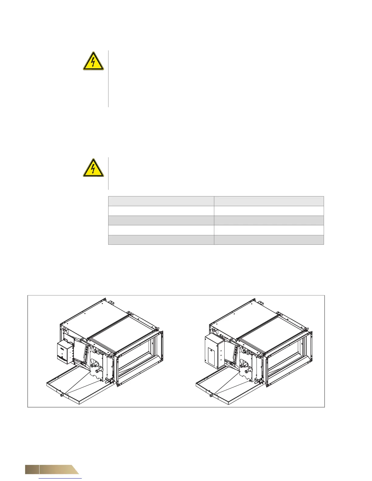
6.2 Terminal box or electric switch cabinet
Depending on the model variant, the HyPower-Geko is delivered with a
– Terminal boxand metal sheet electrical control box
Terminal box
The terminal box contains a terminal block and, depending on the model, additional
electrical parts.
Metal-sheet electric switch cabinet
Danger of electrical current!
The electrical installation of the fan coil unit may only be carried out by qualified
licensed electricians in compliance with this operation manual and the following reg-
ulations:
– VDE regulations, including safety regulations
– Accident prevention regulations
– Installation instructions
Danger of electrical current!
The connection diagrams do not specify any protective measures. Currently valid
standards and regulations must be observed and checked with the local power com-
pany.
Control/power electronics Fusing
MATRIX 2001 B 10 A
MATRIX 3001 B 10 A
MATRIX 4001 B 10 A
Miniature switch C 6 A
Tab. 6-1: Fusing
Fig. 6-1: terminal box/electric control box

 Loading...
